Electrophoretic display key structure

An electrophoretic display and button technology, which is applied in the direction of circuits, electric switches, electrical components, etc., can solve the problems of high cost, achieve good effect, simple and convenient manufacturing

Inactive Publication Date: 2011-07-06
ICHIA TECH
View PDF8 Cites 2 Cited by
  • Summary
  • Abstract
  • Description
  • Claims
  • Application Information

AI Technical Summary

Problems solved by technology

The display-type button disclosed is a single-button structure. In other words, when an electronic produc

Method used


Image

  • Electrophoretic display key structure
  • Electrophoretic display key structure
  • Electrophoretic display key structure

Examples


Embodiment Construction

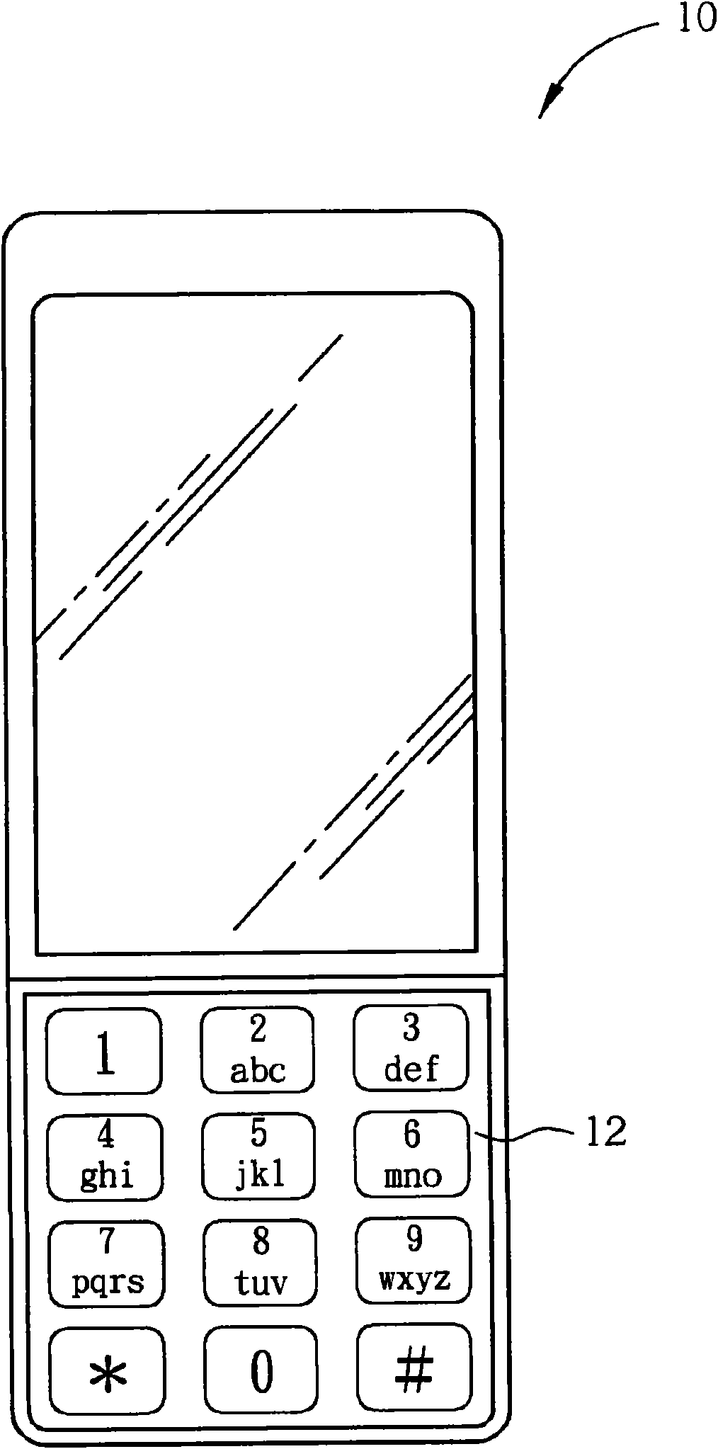
[0037] figure 2 A specific embodiment of the application of the present invention is shown, wherein the mobile phone 10 uses an embodiment of the electrophoretic display key structure 12 according to the present invention as a key. The electrophoretic display button structure of the present invention can also be applied to other electronic products having a button structure as its button structure.

[0038] The structure of the electrophoretic display button according to the present invention will be described in detail below.

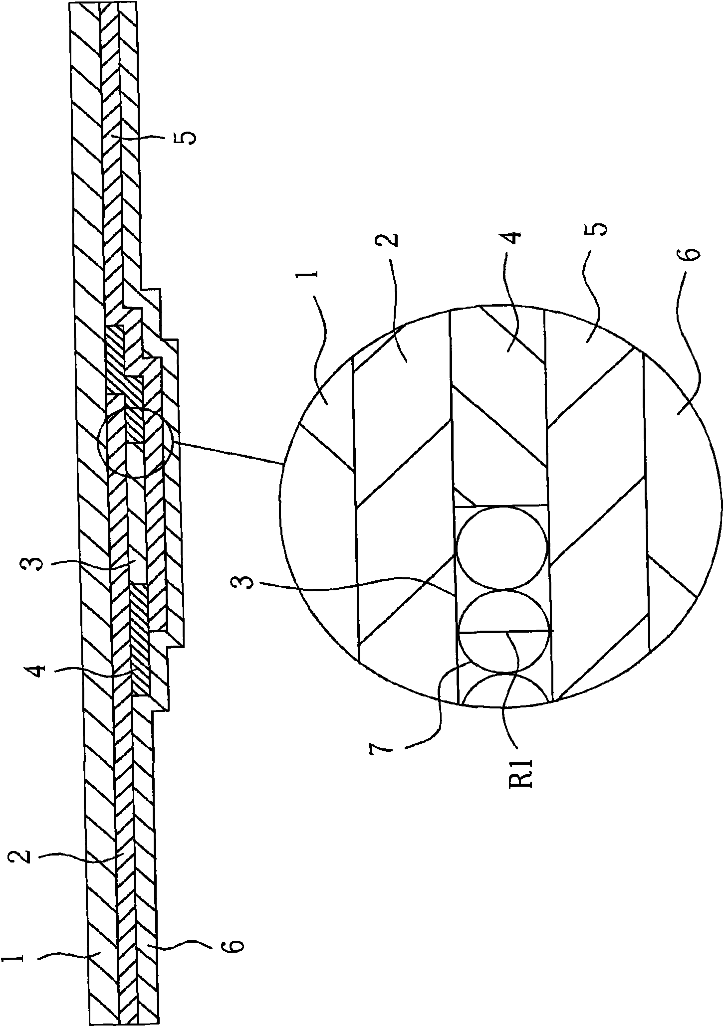
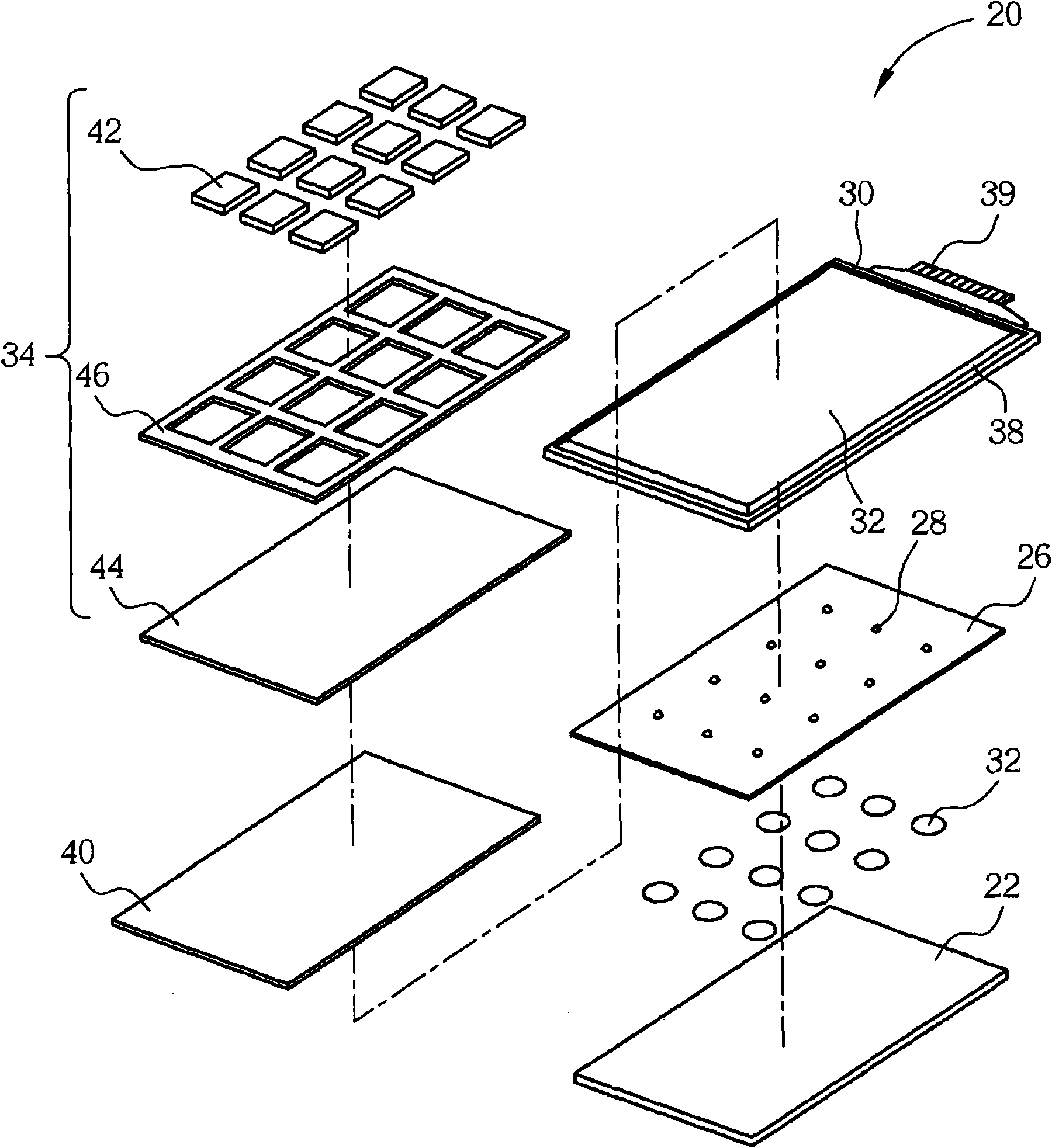
[0039] see image 3 and Figure 4The electrophoretic display button structure 20 includes a first printed circuit board 22 , a plurality of metal domes 24 , a plurality of protrusions 28 , a second printed circuit board 30 , an electrophoretic display film 32 , and a key cap structure 34 . The first printed circuit board 22 can be a flexible printed circuit board on which a printed circuit 36 ​​is disposed. Each metal dome 24 is disposed above the...


PUM


Abstract

The invention discloses an electrophoretic display key structure. The electrophoretic display key structure uses a whole electrophoretic display film to serve as display of a plurality of key patterns, and is positioned on a printed circuit board with pattern electrodes; the whole periphery of the electrophoretic display film is sealed by sealant or a sealing material so as to prevent dampness or pollution, pictures can be displayed excellently, and the structure is easy to manufacture. Patterns to be displayed can be switched according to the mode, so that a user can easily and clearly discriminate words or patterns on the key.

Description

technical field [0001] The invention relates to a button structure, in particular to a button structure using an electrophoretic display film in the structure. Background technique [0002] Electronic products such as cell phones (Cell Phone), personal digital assistants (personal digital assistants, PDAs), etc. are usually provided with keypads. Keypads currently on the market can be divided into metal keypads and generally more common plastic keypads. The patterns of numbers, symbols and English characters on the keypads are usually made on the keycaps by printing or laser etching. On the upper surface, the pattern is easily peeled off and damaged under frequent pressing. In order to protect the pattern and increase the three-dimensional beauty, there is also a technique of forming the pattern on the lower surface of the keycap. Usually on the surface of limited electronic products, in order to save the area occupied by the keypad, each key will be assigned several patte...

Claims


Application Information

Patent Timeline
IPC IPC(8): H01H13/14H01H13/702H01H13/83G02F1/167
Inventor 黄清池
Owner ICHIA TECH
Why Eureka
Try Eureka