Electromagnet device and electromagnetic relay

An electromagnetic relay, electromagnet technology, applied in the direction of electromagnetic relay, electromagnetic relay detailed information, relay, etc., can solve the problem of rotation angle limitation, cannot increase, cannot increase the distance between the opening and closing contacts of electromagnetic relay, etc. The effect of large linear drive distance and increased rotation radius

Inactive Publication Date: 2011-07-06
FUJI ELECTRIC FA COMPONENTS & SYST CO LTD
View PDF5 Cites 4 Cited by
  • Summary
  • Abstract
  • Description
  • Claims
  • Application Information

AI Technical Summary

Problems solved by technology

In addition, the movable iron core portion 56 is rotated by the magnetic attraction force and the repulsive force, so the rotation angle thereof is restricted and cannot be increased.
[0015] Therefore, in the existing electromagnet device, even if the driving force can be obtained, the linear driving distance relative to the movable contact cannot be increased, and there is a problem that the separation distance of the opening and closing contacts of the electromagnetic relay cannot be increased.

Method used


Image

  • Electromagnet device and electromagnetic relay
  • Electromagnet device and electromagnetic relay
  • Electromagnet device and electromagnetic relay

Examples


Embodiment 1

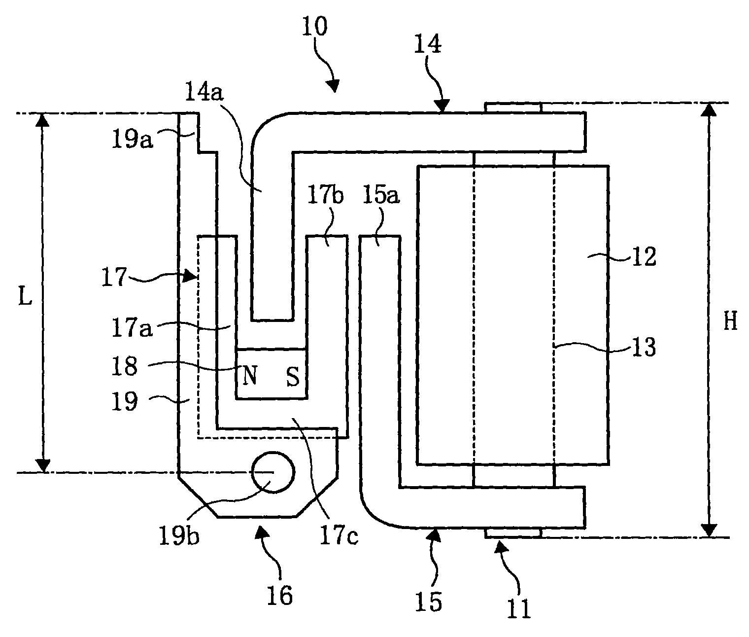
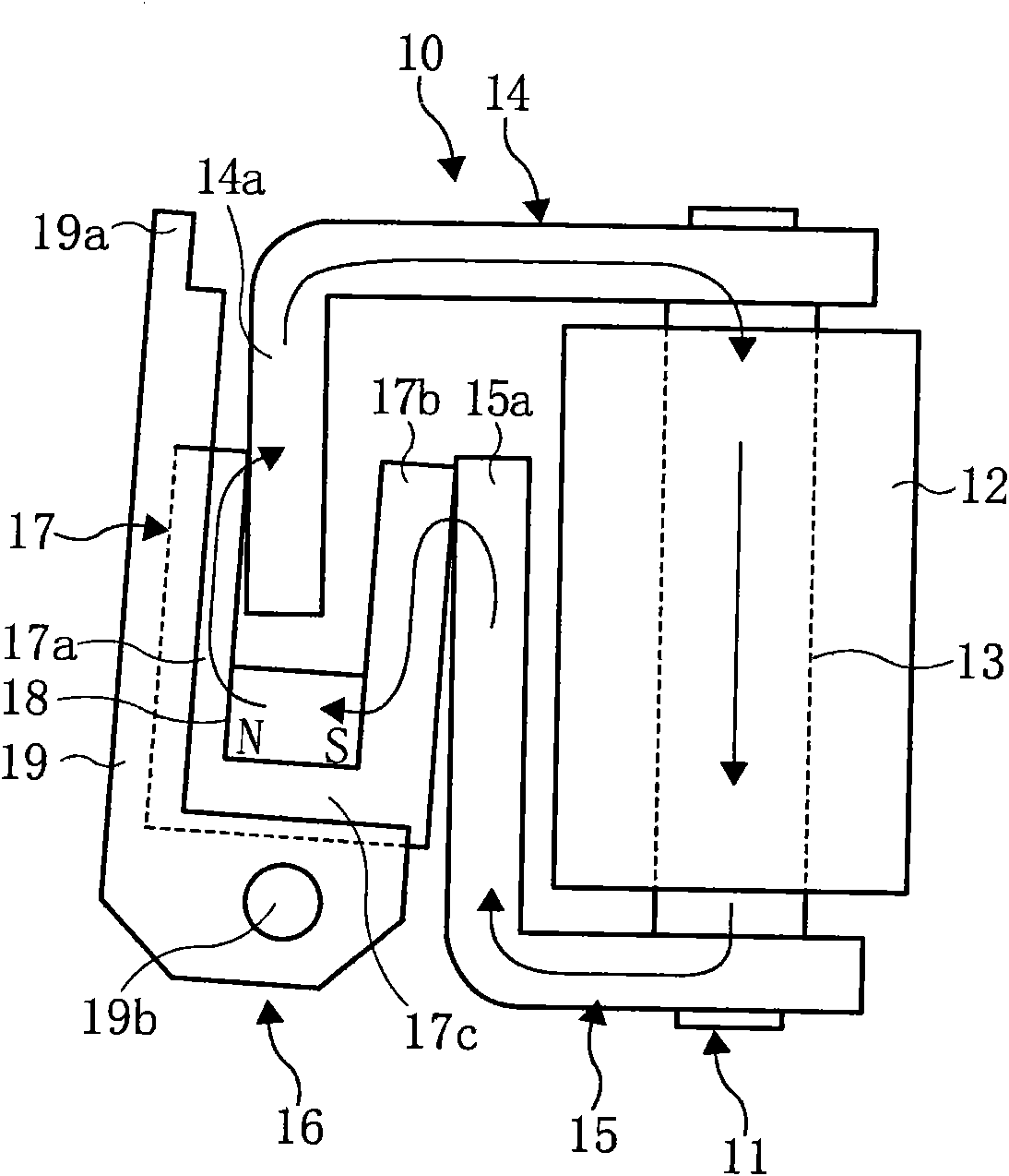
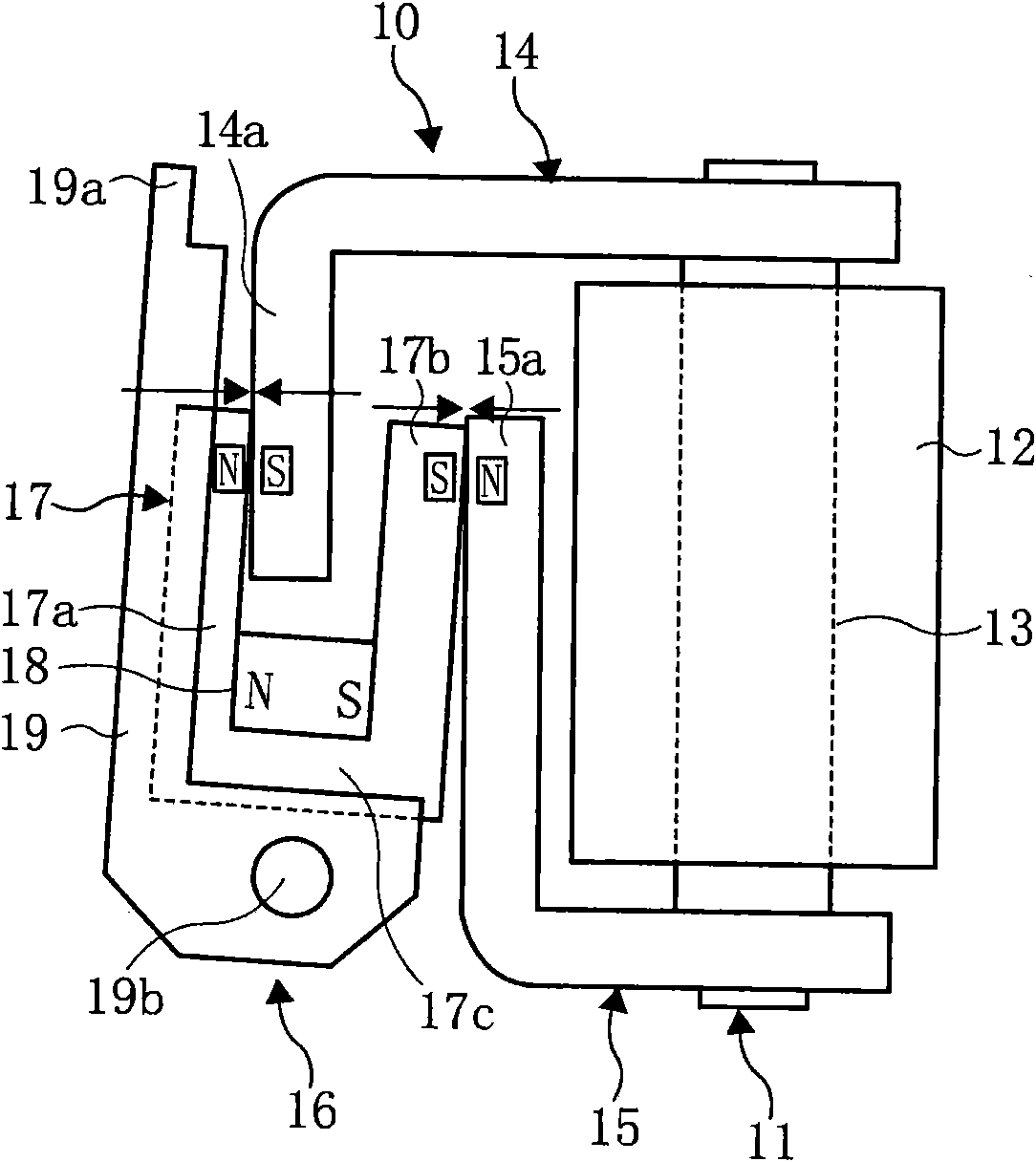
[0061] figure 1 It is a front view showing the configuration of an embodiment of the electromagnet device of the present invention.

[0062] In this figure, reference numeral 10 is an electromagnet device. The electromagnet unit 11 of the electromagnet device 10 is constituted by mechanically and magnetically coupling yokes 14 and 15 to both ends of a core 13 around which an electromagnetic coil 12 is wound. Front end portions 14 a and 15 a of the yokes 14 and 15 , which are bent in the vertical direction, are arranged in parallel at a predetermined distance from each other, and partially overlap each other.

[0063] The movable iron core part 16 includes a movable iron core 17 formed in a U-shape by two iron core legs 17a, 17b arranged in parallel at a certain interval and a connecting leg 17c connecting the lower ends of the iron core legs. The permanent magnet 18 is in contact with the connection leg 17c, and is installed between the parallel core legs 17a and 17b of the...

Embodiment 2

[0076] Figure 8 and Figure 9 It shows an example of the electromagnetic relay using the electromagnet device of the present invention.

[0077] In the figure, reference numeral 10 is an electromagnet device having the same configuration as the above-mentioned electromagnet device, and reference numeral 20 is an opening and closing contact mechanism of an electromagnetic relay.

[0078] The opening and closing contact mechanism 20 includes two groups of normally open switches made of a spring material, the front end of which is composed of a fixed contact piece 22a with a fixed contact 21a and a movable contact piece 24a with a movable contact 23a. Contact mechanism (so-called a contact mechanism). And, it includes a group of normally closed opening and closing contact mechanisms ( The so-called b contact mechanism).

[0079] The base ends of the fixed contact pieces 22a, 22b and the movable contact pieces 24a, 24b are respectively embedded in an insulating base 27 made o...


PUM


Abstract

The invention provides an electromagnet device capable of increasing the driving force and the linear driving distance and an electromagnetic relay capable of increasing the distance between the switch contact points. The movable iron core of a movable iron core part is formed by the u-shaped iron core of a built-in permanent magnet and the movable iron core part is driven by an electromagnet. The yokes of the movable iron core and the electromagnet are inserted into each other to be assembled, so that one of the core pins parallel to the movable iron core is inserted between the front ends of two parallel yokes of the electromagnet. Meanwhile, the front end of one of the yokes is inserted between the two parallel core pins of the movable iron core. In addition, the lower end of the movable iron core part is rotatably supported.

Description

technical field [0001] The present invention relates to an electromagnet device and an electromagnetic relay using the same. Background technique [0002] In the electromagnetic relay driven by the electromagnet device, the movable iron core part that can be rotatably supported is generally rotated by the magnetic attraction force of the electromagnet and the elastic force of the return spring, and the contact mechanism is directly or indirectly driven by the rotating force, and the contact mechanism can be driven by the rotating force. The opening and closing contacts composed of moving contacts and fixed contacts perform opening and closing. [0003] In particular, in high-standard electromagnetic relays called safety relays, in order to reduce opening and closing failures caused by welding of the switching contacts, even if the switching contacts are welded, they can be peeled off and opened and closed. It is driven by an electromagnet device with a large driving force. ...

Claims


Application Information

Patent Timeline
Patent Type & Authority Applications(China)
IPC IPC(8): H01H50/16
Inventor 藤田贤
Owner FUJI ELECTRIC FA COMPONENTS & SYST CO LTD
Why Eureka
Try Eureka