X-ray tube control method and device, driving device, and X-ray generating device
A technology of an X-ray tube and a control method, which is applied in the field of X-ray generating devices, can solve the problems of increasing the heat dissipation pressure of the X-ray tube, and cannot further improve the rotational driving force, and achieves rapid braking, increasing the rotational speed, and increasing the heat dissipation capacity. Effect
- Summary
- Abstract
- Description
- Claims
- Application Information
AI Technical Summary
Problems solved by technology
Method used
Image
Examples
Embodiment 1
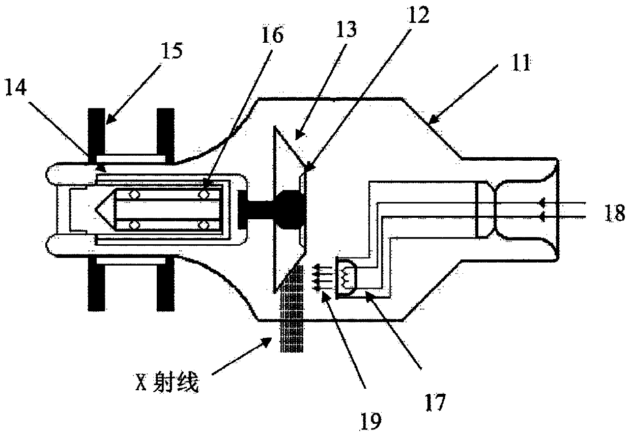
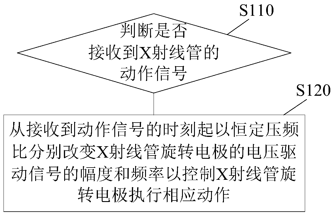
[0039] figure 2 A flow chart of an X-ray tube control method according to an embodiment of the present invention is shown. This control method can be used as Figure 12 shown in the X-ray generating device, and is used to control such as figure 1 The rotating electrode of the X-ray tube, the rotating electrode can be such as figure 1 The anode rotating electrode shown may also be the cathode as the rotating electrode, which is not limited in this application. Such as figure 2 As shown, the method includes the following steps:
[0040] S110: Determine whether an action signal of the X-ray tube is received. When an action signal of the X-ray tube is received, step S120 is performed; otherwise, no operation is performed.
[0041] S120: Change the amplitude and frequency of the voltage driving signal of the X-ray tube rotating electrode at a constant voltage-frequency ratio from the time the action signal is received to control the X-ray tube rotating electrode to perform ...
Embodiment 2
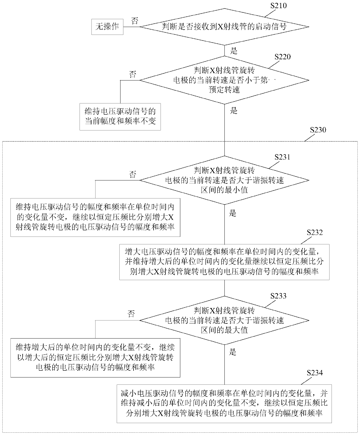
[0050] image 3 A flow chart of another method for controlling an X-ray tube according to an embodiment of the present invention is shown. This control method can be used as Figure 12 shown in the X-ray generating device, and is used to control such as figure 1 The rotating electrode of the X-ray tube, the rotating electrode can be such as figure 1 The anode rotating electrode shown may also be the cathode as the rotating electrode, which is not limited in this application. Such as image 3 As shown, the method includes the following steps:
[0051] S210: Determine whether a start signal of the X-ray tube is received. When the start signal of the X-ray tube is received, step S220 is performed; otherwise, no operation is performed. The starting signal can be input by human control, or can be automatically generated by the equipment.
[0052] S220: Determine whether the current rotational speed of the rotating electrode of the X-ray tube is less than a first predetermine...
Embodiment 3
[0066] Figure 7 A flow chart of another method for controlling an X-ray tube according to an embodiment of the present invention is shown. This control method can be used as Figure 12 shown in the X-ray generating device, and is used to control such as figure 1 The rotating electrode of the X-ray tube, the rotating electrode can be such as figure 1 The anode rotating electrode shown may also be the cathode as the rotating electrode, which is not limited in this application. Such as Figure 7 As shown, the method includes the following steps:
[0067] S310: Determine whether a braking signal of the X-ray tube is received. When the braking signal of the X-ray tube is received, step S320 is performed; otherwise, no operation is performed. The brake signal can be input by human control, or automatically generated by the equipment.
[0068] S320: Determine whether the current rotational speed of the rotating electrode of the X-ray tube is greater than a second predetermine...
PUM
 Abstract
Description
Claims
Application Information
 - R&D
- Intellectual Property
- Life Sciences
- Materials
- Tech Scout
- Unparalleled Data Quality
- Higher Quality Content
- 60% Fewer Hallucinations
Browse by: Latest US Patents, China's latest patents, Technical Efficacy Thesaurus, Application Domain, Technology Topic, Popular Technical Reports.
© 2025 PatSnap. All rights reserved.Legal|Privacy policy|Modern Slavery Act Transparency Statement|Sitemap|About US| Contact US: help@patsnap.com


