
X-ray tube control method, device, driving device and X-ray generating device

A technology of an X-ray tube and a control method, which is applied in the field of X-ray generating devices, can solve the problems of increasing the heat dissipation pressure of the X-ray tube, and cannot further improve the rotational driving force, and achieves rapid braking, increasing the rotational speed, and increasing the heat dissipation capacity. Effect

Active Publication Date: 2018-01-26
SUZHOU POWERSITE ELECTRIC CO LTD
View PDF5 Cites 7 Cited by
  • Summary
  • Abstract
  • Description
  • Claims
  • Application Information

AI Technical Summary

Problems solved by technology

[0007] In view of this, the embodiment of the present invention provides an X-ray tube control method and device, a driving device, and an X-ray generating device to solve the problem that the existing control method of variable voltage and constant frequency increases the heat dissipation pressure of the X-ray tube but cannot further The Problem with Improving Rotational Driving Force

Method used


Image

  • X-ray tube control method, device, driving device and X-ray generating device
  • X-ray tube control method, device, driving device and X-ray generating device
  • X-ray tube control method, device, driving device and X-ray generating device

Examples


Embodiment 1

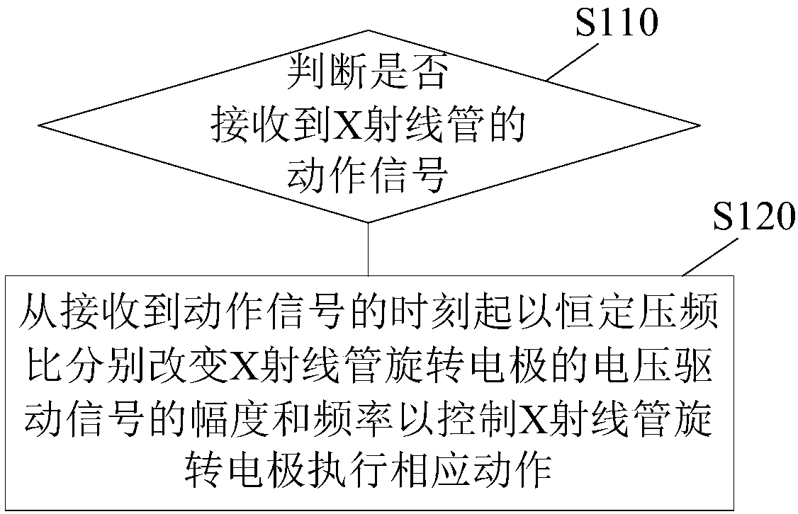
[0039] figure 2 A flow chart of an X-ray tube control method according to an embodiment of the present invention is shown. This control method can be used as Figure 12 shown in the X-ray generating device, and is used to control such as figure 1 The rotating electrode of the X-ray tube, the rotating electrode can be such as figure 1 The anode rotating electrode shown may also be the cathode as the rotating electrode, which is not limited in this application. Such as figure 2 As shown, the method includes the following steps:

[0040] S110: Determine whether an action signal of the X-ray tube is received. When an action signal of the X-ray tube is received, step S120 is performed; otherwise, no operation is performed.

[0041] S120: Change the amplitude and frequency of the voltage driving signal of the X-ray tube rotating electrode at a constant voltage-frequency ratio from the time the action signal is received to control the X-ray tube rotating electrode to perform ...

Embodiment 2

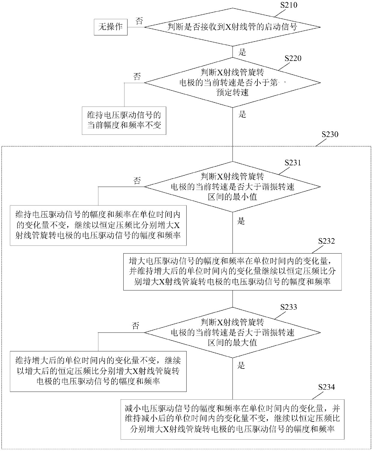
[0050] image 3 A flow chart of another method for controlling an X-ray tube according to an embodiment of the present invention is shown. This control method can be used as Figure 12 shown in the X-ray generating device, and is used to control such as figure 1 The rotating electrode of the X-ray tube, the rotating electrode can be such as figure 1 The anode rotating electrode shown may also be the cathode as the rotating electrode, which is not limited in this application. Such as image 3 As shown, the method includes the following steps:

[0051] S210: Determine whether a start signal of the X-ray tube is received. When the start signal of the X-ray tube is received, step S220 is performed; otherwise, no operation is performed. The starting signal can be input by human control, or can be automatically generated by the equipment.

[0052] S220: Determine whether the current rotational speed of the rotating electrode of the X-ray tube is less than a first predetermine...

Embodiment 3

[0066] Figure 7 A flow chart of another method for controlling an X-ray tube according to an embodiment of the present invention is shown. This control method can be used as Figure 12 shown in the X-ray generating device, and is used to control such as figure 1 The rotating electrode of the X-ray tube, the rotating electrode can be such as figure 1 The anode rotating electrode shown may also be the cathode as the rotating electrode, which is not limited in this application. Such as Figure 7 As shown, the method includes the following steps:

[0067] S310: Determine whether a braking signal of the X-ray tube is received. When the braking signal of the X-ray tube is received, step S320 is performed; otherwise, no operation is performed. The brake signal can be input by human control, or automatically generated by the equipment.

[0068] S320: Determine whether the current rotational speed of the rotating electrode of the X-ray tube is greater than a second predetermine...


PUM


Abstract

The invention discloses an X-ray tube control method, an X-ray tube control device, an X-ray tube control driving device and an X-ray generating device. The control method includes the following stepsthat: whether action signals of an X-ray tube are received is judged; and when the action signals of the X-ray tube are received, the amplitude and frequency of the voltage driving signals of the rotating electrode of the X-ray tube are changed with a constant voltage-frequency ratio from a time point when the action signals are received, so that the rotating electrode of the X-ray tube is controlled to execute corresponding actions, wherein the constant pressure-frequency ratio refers to a condition that the ratio of the amplitude change value to frequency change value of the voltage drivingsignals of the rotating electrode of the X-ray tube is a constant value. According to the control method of the invention, the amplitude and frequency of the voltage driving signals are increased with the constant voltage-frequency ratio, so that magnetic saturation phenomena can be avoided, the rotational driving force of the motor can be increased, the rotating speed of the motor can be improved, and therefore, the heat dissipation capacity of the rotating electrode can be increased; and the amplitude and frequency of the voltage driving signals can be decreased with the constant voltage-frequency ratio, so that hysteresis can be avoided, and therefore, the rotational driving force of the electrode can be decreased fast, and rapid braking can be realized.

Description

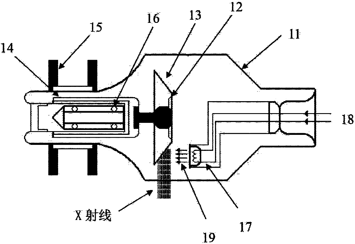
technical field [0001] The invention relates to the technical field of X-ray generators, in particular to a control method and device for an X-ray tube, a driving device, and an X-ray generator. Background technique [0002] X-ray tube (also known as tube) is a key component for generating X-rays (also known as exposure), and it is also an expensive and short-lived consumable. Because the electrons bombard a point on the target surface, it is easy to cause the temperature of the local point to be too high to melt and damage, so a rotating anode target tube is designed for this purpose. [0003] Such as figure 1 As shown, the structure of the rotating anode X-ray tube specifically includes a vacuum tube 11 made of glass and an AC motor connected to the vacuum tube 11. The AC motor includes three parts: an electromagnetic stator 15, a rotor 14 and a bearing 16. A vacuum tube 11 is provided with a The anode target 12 made of tungsten metal and in the shape of a trapezoidal di...

Claims


Application Information

Patent Timeline
IPC IPC(8): H05G1/32H05G1/46
Inventor 陈飞范声芳黄强韦慧明王万全
Owner SUZHOU POWERSITE ELECTRIC CO LTD
Learn More