Smooth narrow pulse compensating method of FPGA in frequency converter

A compensation method and narrow pulse technology, applied in the field of narrow pulse compensation, can solve the problems of reduced output starting torque, affecting system operation performance, three-phase voltage unbalance, etc. The effect of improved performance

Inactive Publication Date: 2011-07-06
CHINESE ELECTRICAL EQUIP GRP CO LTD
View PDF1 Cites 9 Cited by
  • Summary
  • Abstract
  • Description
  • Claims
  • Application Information

AI Technical Summary

Problems solved by technology

If there is no compensation after the narrow pulse is directly deleted, the output waveform will be severely distorted at low frequencies, the output starting torque will decrease, the voltage harmonics will increase, the three-phase voltage will be unbalanced, and even harmonics will appear. These problems will seriously affect the Reduce system performance and reduce system efficiency

Method used


Image

  • Smooth narrow pulse compensating method of FPGA in frequency converter
  • Smooth narrow pulse compensating method of FPGA in frequency converter
  • Smooth narrow pulse compensating method of FPGA in frequency converter

Examples


Embodiment Construction

[0019] Below in conjunction with accompanying drawing, the utility model is further explained.

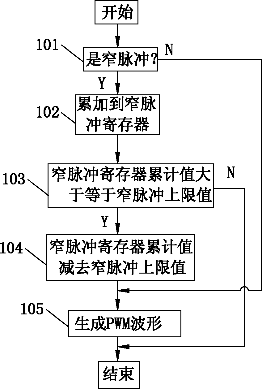
[0020] Such as figure 1 Shown, the compensation method that FPGA realizes smooth narrow pulse in the frequency converter of the present invention comprises the steps:

[0021] 1. At the beginning, inside the FPGA (Field Programmable Logic Gate Array), it is judged whether the value of the input modulation wave is a narrow pulse? Generally, the upper limit of the narrow pulse is 3us, if it is greater than or equal to 3us, it is not a narrow pulse; if it is less than 3us, it is a narrow pulse.

[0022] If the input modulation wave is not a narrow pulse, then go to step 105, the FPGA outputs a PWM waveform, the value of the output modulation wave is the value of the input modulation wave, and one cycle ends. That is, if the value of the input modulation wave is 4us, the FPGA outputs a 4us PWM waveform; if the value of the input modulation wave is 3us, the FPGA outputs a 3us PWM wave...


PUM


Abstract

The invention discloses a smooth narrow pulse compensating method of an FPGA (field programmable gate array) in a frequency converter, which comprises the steps as follows: judging whether an input modulating wave is a narrow pulse, if not, outputting the waveform, and if the value is stored in a narrow pulse register, not generating a waveform currently; inputting the modulating wave again, and judging whether the value is a narrow pulse, if not, outputting the waveform, if yes, accumulating the value; judging whether the sum of accumulated values is larger than or equal to the narrow pulse upper limit, if yes, outputting the waveform; and if the modulating wave is a narrow pulse, and the sum of accumulated values of the narrow pulse register is smaller than the narrow pulse upper limit, accumulating the current value in the narrow pulse register, and not outputting the wave. By taking the measure, an additional hardware circuit is not needed, thus being capable of guaranteeing smooth waveforms to be output at a position of a sinusoidal wave at which a narrow pulse is generated, effectively reducing the switching frequency of a power device, the heat generated by the device and harmonic content of the system, increasing the effective output level of the device, and improving the efficiency of the whole system.

Description

technical field [0001] The invention relates to a narrow pulse compensation method, in particular to a compensation method for FPGA in a frequency converter to realize smooth narrow pulse. Background technique [0002] The invention relates to a medium-voltage, high-power frequency converter drive system, because there are narrow pulses in the drive waveform of the power electronic switching device, especially at low frequency, that is, when the drive signal is not fully turned on, the drive is turned off. The signal turns it off again, so that the switching power device works in the amplified area and does not enter the saturated working area, resulting in increased switching loss, causing the device to heat up, and unable to output an effective level, which affects the life of the device. At the same time, it introduces interference and causes A large impact on the reverse diode leads to an increase in the total harmonic distortion (THD) of the output line voltage, increas...

Claims


Application Information

Patent Timeline
Patent Type & Authority Applications(China)
IPC IPC(8): H02M1/12H02P27/04
CPCY02P80/10
Inventor 常东来祖芳李弓祥
Owner CHINESE ELECTRICAL EQUIP GRP CO LTD
Why Eureka
Try Eureka