Disk drive

Inactive Publication Date: 2007-11-01
WESTERN DIGITAL TECH INC
View PDF3 Cites 3 Cited by
  • Summary
  • Abstract
  • Description
  • Claims
  • Application Information

AI Technical Summary

Benefits of technology

[0005]Embodiments of the present invention provide a disk drive that ensures quieter rotational acceleration of a recording disk. According to the particular embodiments disclosed in FIGS. 1 and 2, a hard disk drive 1A detects the vibration of an enclosure 2 by monitoring via a driver 72 a counter electromotive volta

Problems solved by technology

As a result, quietness during operation of the hard disk drive is increasingly being demanded.
Incidentally, disk drives are liable to generate noise particularly due to the vibration caused by the rotation of a spindle motor during the rotational acceleration (during so-called spinup) caused by the fact that the recording disk is accelerated from a stand

Method used


Image

  • Disk drive
  • Disk drive
  • Disk drive

Examples


first embodiment

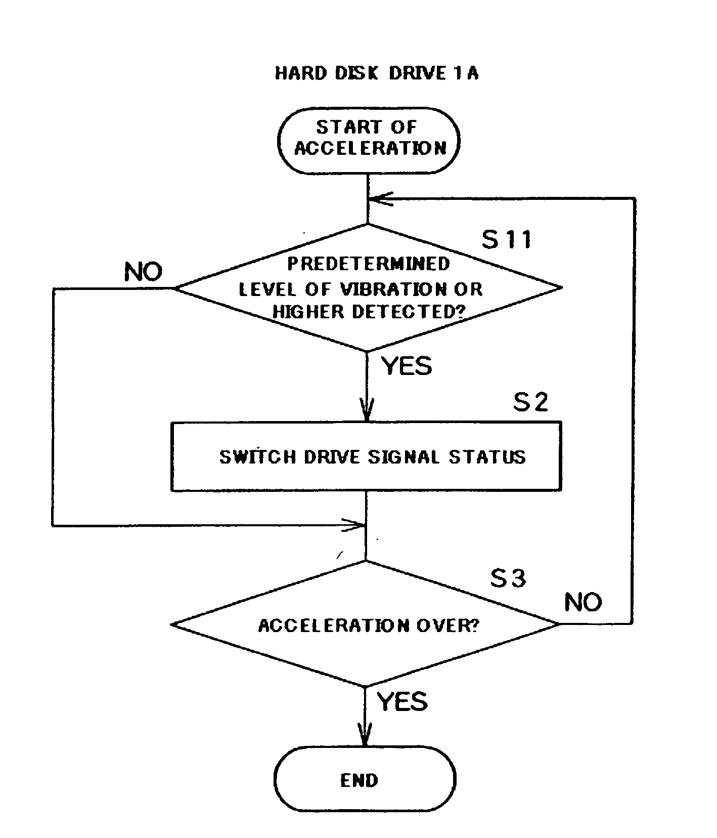
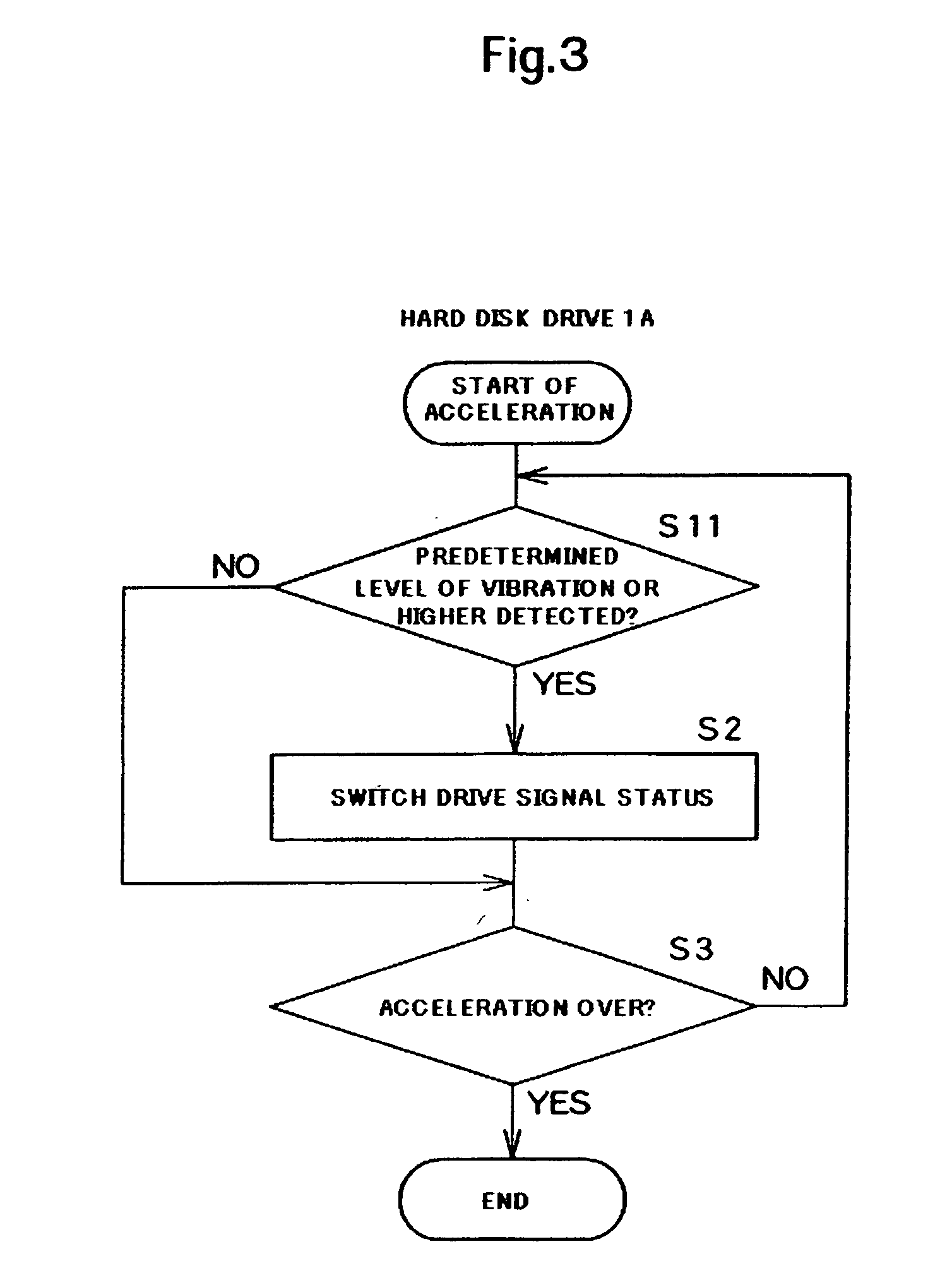
[0037]FIG. 3 shows a flowchart representing the operation of the hard disk drive 1A of the first embodiment. When the processing unit 71A of the control device 7A detects via the driver 72, a predetermined level of vibration or higher in the enclosure 2 (S11: YES), the processing unit switches the status of a drive signal applied to the spindle motor SPM so as to reduce the vibration of the enclosure 2 (S2). Here, the vibration level used as a threshold value can be determined as appropriate in accordance with the silence level required.

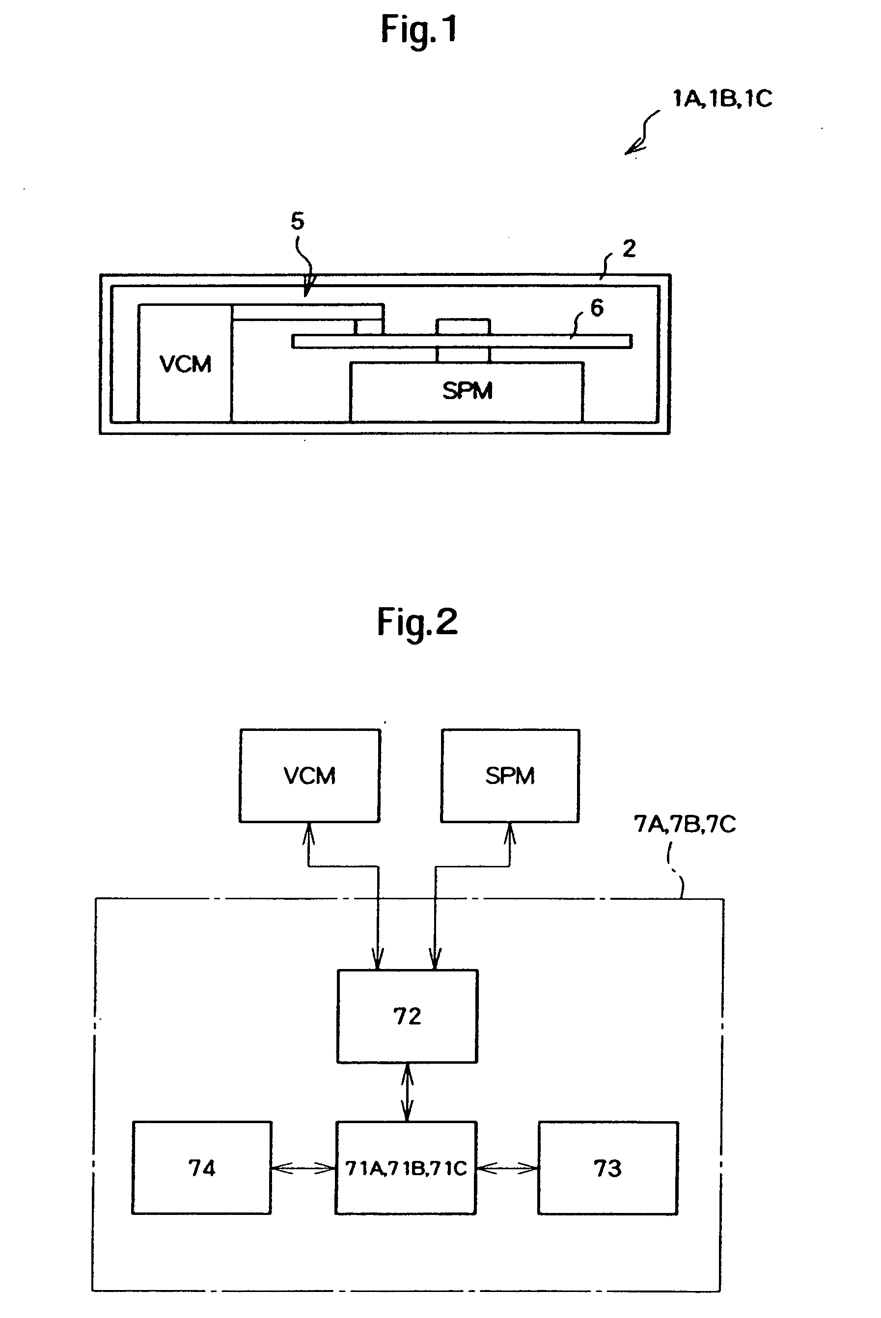
[0038]In Step S11, the vibration of the enclosure 2 can be detected by monitoring a counter electromotive voltage generated in a motor different from the spindle motor SPM housed in the enclosure. Here, the counter electromotive voltage generated in the voice coil motor VCM is monitored by the driver 72. That is, the driver 72 serves as a detecting device.

[0039]That is, if the enclosure 2 vibrates as a result of the rotation of the spindle motor SPM,...

second embodiment

[0053]FIG. 4 shows a flowchart representing the operation of the hard disk drive 1B of the second embodiment. It is to be noted that the same steps as those in the first embodiment are denoted with the same reference numerals for omission of detailed description. The processing unit 71B of the control device 7B switches the status of the drive signal applied to the spindle motor SPM so as to reduce the vibration of the enclosure 2 (S2) if the rotational speed of the spindle motor falls within the rotational speed range causing a predetermined level of vibration or higher in the enclosure 2 (S21: YES).

[0054]The processing unit 71B of the control device 7B monitors the rotational speed of the spindle motor SPM based on the signal detected from the motor by the driver 72. In Step S21, therefore, the processing unit 71B determines whether the monitored current rotational speed falls within the range causing a predetermined level of vibration or higher in the enclosure 2.

[0055]The memory...

third embodiment

[0060]FIG. 5 shows a flowchart representing the operation of the hard disk drive 1C of the third embodiment. It is to be noted that the same steps as those in the first embodiment are denoted with the same reference numerals for omission of detailed description. The processing unit 71C of the control device 7C switches the status of the drive signal applied to the spindle motor SPM so as to reduce the vibration of the enclosure 2 (S2) if the rotational speed of the spindle motor falls within the rotational speed range causing a predetermined level of vibration or higher in the enclosure 2 (S21: YES). Then if the processing unit 71C detects via the driver 72 a predetermined level of vibration or higher in the enclosure 2 (S11: YES), the processing unit switches the status of the drive signal applied to the spindle motor SPM so as to reduce the vibration of the enclosure 2 (S2).

[0061]That is, in the presence of a predetermined level of initial vibration or higher during spinup, the pr...


PUM


Abstract

Embodiments in accordance with the present invention provide a disk drive that ensures quieter rotational acceleration of a recording disk. Certain embodiments relate to a hard disk drive that detects the vibration of an enclosure by monitoring, via a driver, a counter electromotive voltage generated in a voice coil motor. If the hard disk drive detects a predetermined level of vibration or higher in the enclosure, it switches the status of a drive signal applied to a spindle motor so as to reduce the current level or smooth the waveform. This ensures reduced vibration of the enclosure.

Description

CROSS-REFERENCE TO RELATED APPLICATION[0001]The instant nonprovisional patent application claims priority to Japanese Application No. 2006-122692, filed Apr. 26, 2006 and incorporated by reference in its entirety herein for all purposes.BACKGROUND OF THE INVENTION[0002]Recent years have seen the application of disk drives such as hard disk drives, not only to computers, but also to other areas including home electronic appliances. As a result, quietness during operation of the hard disk drive is increasingly being demanded.[0003]Incidentally, disk drives are liable to generate noise particularly due to the vibration caused by the rotation of a spindle motor during the rotational acceleration (during so-called spinup) caused by the fact that the recording disk is accelerated from a standstill to a predetermined rotational speed by the spindle motor. More specifically, when the recording disk begins to rotate from a standstill, friction acting on a rotation mechanism changes. This lea...

Claims


Application Information

Patent Timeline
IPC IPC(8): G11B15/46
CPCG11B19/28G11B19/04
Inventor HAYASHI, YUKIKOYONEDA, ISAOIKEDO, GAKUKOIDE, NOBUHISAAMARI, YUHJI
Owner WESTERN DIGITAL TECH INC
Why Eureka
Try Eureka