Switching power supply circuit

A technology of switching power supply circuits and switching devices, which is applied in the directions of high-efficiency power electronic conversion, electrical components, and adjustment of electrical variables, and can solve problems such as reduction

Inactive Publication Date: 2006-03-22
SONY CORP
View PDF1 Cites 12 Cited by
  • Summary
  • Abstract
  • Description
  • Claims
  • Application Information

AI Technical Summary

Problems solved by technology

[0043] First, in response to the performance of CV control operation, when the load becomes larger, the switching frequency fs decreases

Method used


Image

  • Switching power supply circuit
  • Switching power supply circuit
  • Switching power supply circuit

Examples


Embodiment Construction

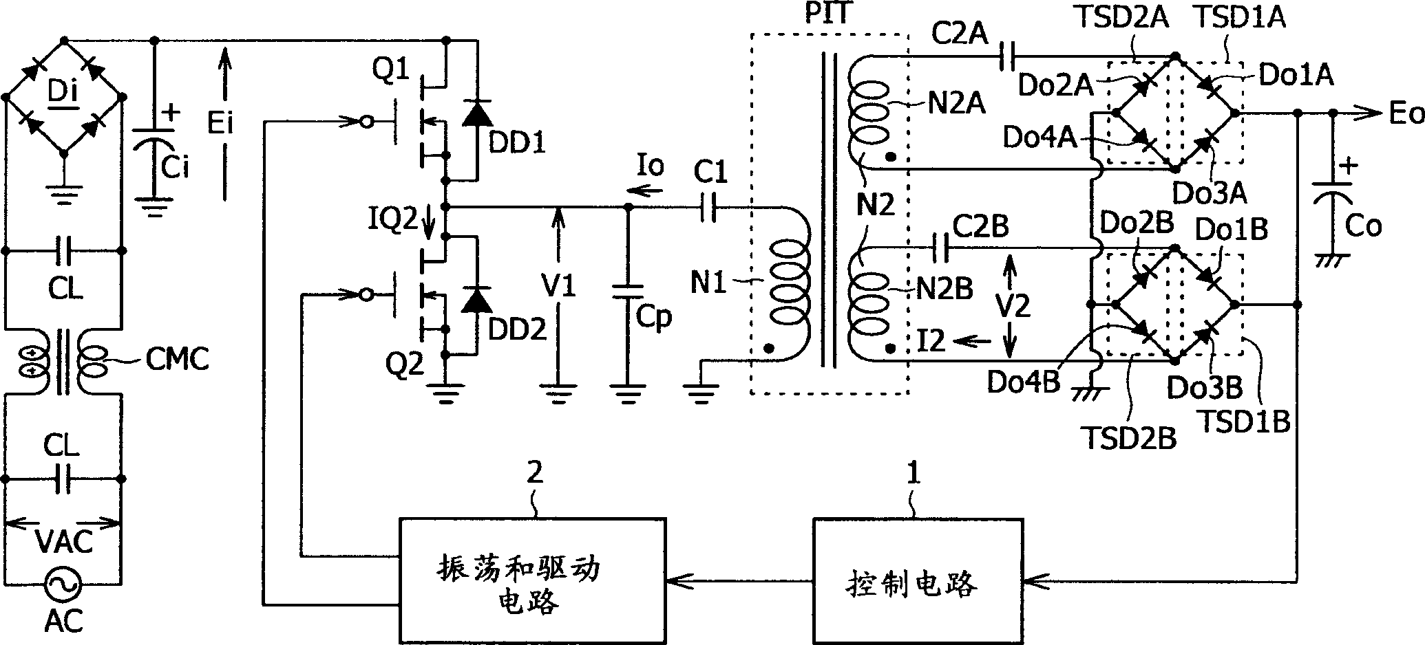
[0104] figure 1 An example of the structure of the switching power supply circuit to which the present invention is applied is given. refer to figure 1 , the power supply circuit shown includes a combination of a partial voltage resonance circuit and a half-bridge coupling type current resonance type converter as its basic structure on the primary side.

[0105] The power supply circuit of this first embodiment has a structure ready for use in a wide range by which it can be operated with AC 100V type and AC 200 type industrial AC power input. Furthermore, in terms of appropriate load power, the power supply circuit can be prepared for a varying range of load power Po, for example, from Po=about 150W to 0W (no load). Also in this case, with reference to the above Figure 14 The situation is the same for the described circuit, a secondary side DC output voltage Eo of eg approximately 25V is likewise obtainable.

[0106] Especially at figure 1 In the power supply circuit ...


PUM


Abstract

A power supply circuit is disclosed which performs constant voltage control by switching frequency control and is ready for a wide range while the necessary control range of the switching frequency control is reduced. The circuit includes a primary side series resonance circuit forming a current resonance type converter, and a secondary side series resonance circuit formed from secondary windings and secondary side series resonance capacitors while a coupling type resonance circuit by electromagnetic coupling of an insulating converter transformer is formed. To obtain a single-humped characteristic from the coupling type resonance circuit, a gap of approximately 1.6 mm is formed in the core of the insulating converter transformer so as to achieve a coupling coefficient of 0.65 or less. A secondary side DC output voltage is produced from outputs of the secondary windings so as to cope with a heavy load condition.

Description

[0001] Cross References to Related Applications [0002] The present invention contains subject matter related to Japanese Patent Application No. JP2004-271920 filed in the Japan Patent Office in Sep. 2004, the entire content of which is hereby incorporated by reference. technical field [0003] This invention relates to a switching power supply circuit provided as a power supply in various electronic equipment blocks. [0004] Meanwhile, the assignee of this patent application has proposed various power supply circuits in which a resonance type converter is provided on the primary side. Background technique [0005] Figure 14 A circuit diagram of an example of a switching power supply circuit including a resonant type converter and which is formed in accordance with an invention previously filed by the assignee of the present application is given. [0006] refer to Figure 14 , the power supply circuit shown includes a switching converter configured to couple its bias vol...

Claims


Application Information

Patent Timeline
Patent Type & Authority Applications(China)
IPC IPC(8): H02M3/28H02M3/338H02M7/48H02M7/5383
CPCH02M2007/4815H02M3/3376Y02B70/1441Y02B70/1491H02M2001/0058H02M1/0058Y02B70/10H02M3/28
Inventor 安村昌之
Owner SONY CORP
Why Eureka
Try Eureka