Supercharge Your Innovation With Domain-Expert AI Agents!

Pulse generating circuit

A technology for generating circuits and pulses, applied in the field of pulse generating circuits, can solve problems such as inability to obtain correct pulse signals, and achieve accurate pulses and simple effects.

Active Publication Date: 2011-07-06
SHANGHAI HUAHONG GRACE SEMICON MFG CORP
View PDF0 Cites 6 Cited by
  • Summary
  • Abstract
  • Description
  • Claims
  • Application Information

AI Technical Summary

Problems solved by technology

[0002] The existing pulse generation circuit usually uses the input signal and its delayed signal to do a logic operation to generate it, which requires that the input signal cannot change during the delay process. If the input signal changes during the delay process and delays The subsequent signal has no time to change, which will eventually lead to the inability to obtain the correct pulse signal

Method used


Image

  • Pulse generating circuit
  • Pulse generating circuit
  • Pulse generating circuit

Examples


Embodiment Construction

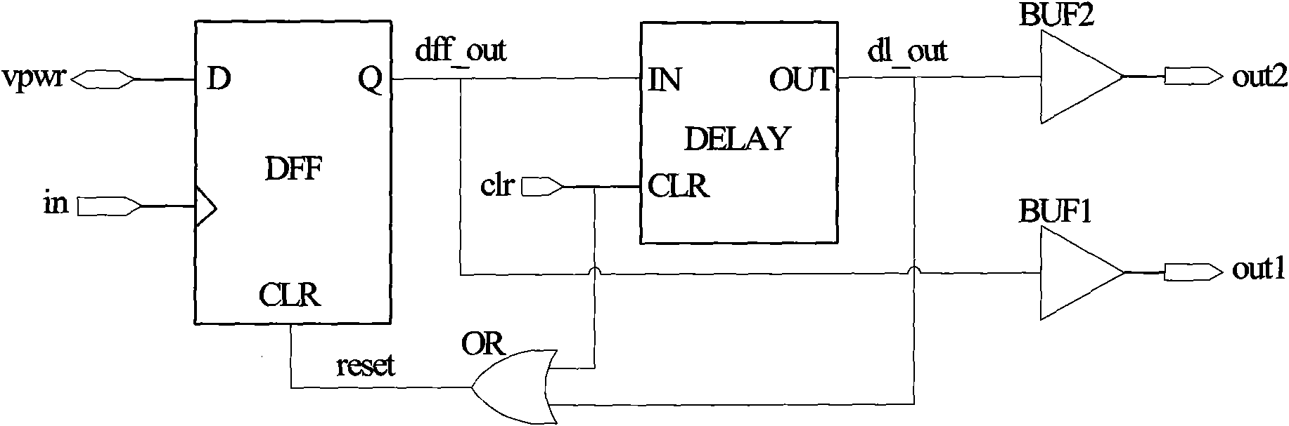
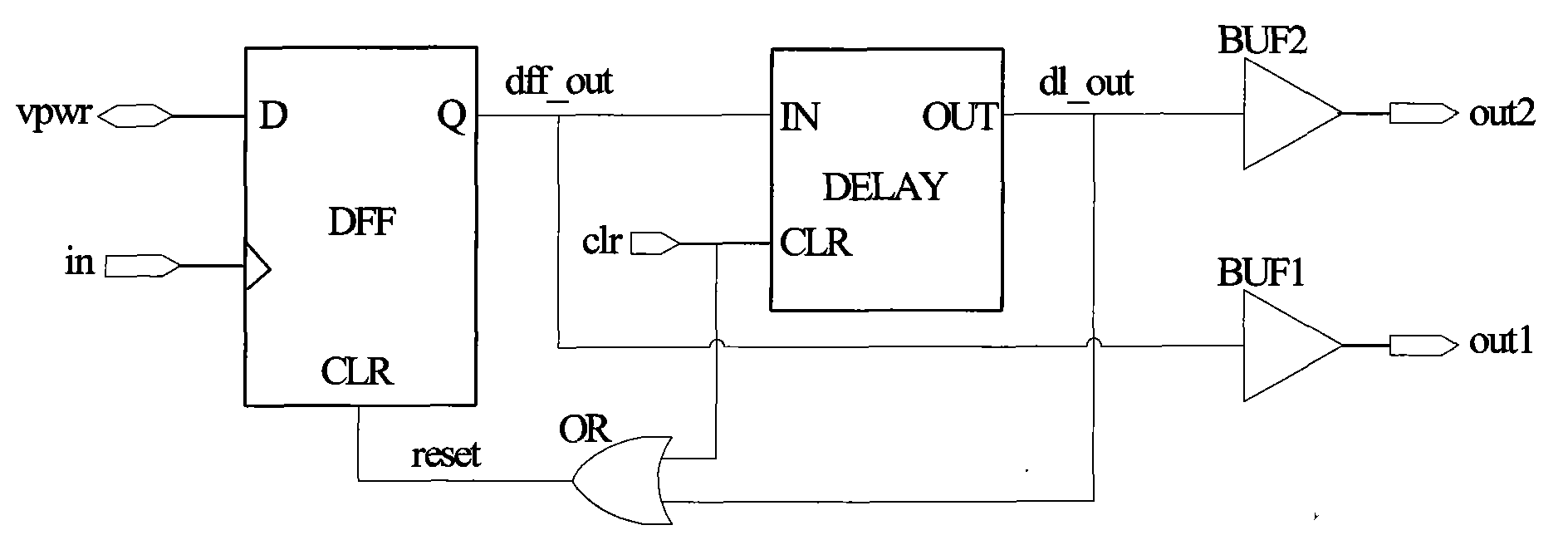
[0015] An embodiment of the pulse generating circuit of the present invention is figure 1 shown. It includes a D flip-flop DFF, a delay circuit DELAY, a logical OR gate OR, a first buffer BUF1, and a second buffer BUF2; the data input terminal D of the D flip-flop DFF is connected to the power supply voltage vpwr, and the clock control terminal CP Connect the input signal in, the data output terminal Q is connected to the input terminal IN of the delay circuit DELAY and the input terminal of the first buffer BUF1, the clearing terminal CLR of the delay circuit DELAY is connected to the clearing signal clr, and the output terminal OUT is connected to the first buffer BUF1 The input terminal of the second buffer BUF2 and one input terminal of the OR gate OR, the other input terminal of the OR gate OR is connected to the clearing signal clr, and the output terminal is connected to the clearing terminal CLR of the D flip-flop DFF.

[0016] The delay circuit DELAY, when its input ...


PUM


Abstract

The invention discloses a pulse generating circuit comprising a trigger, a delay circuit, an OR door, a first buffer and a second buffer, wherein the data input end of the trigger is connected with a power supply voltage, a clock control end of the trigger is connected with an input signal, and a data output end of the trigger is connected with the input end of the delay circuit and the input endof the first buffer; a zero clearing end of the delay circuit is connected with a zero clearing signal, and an output end of the delay circuit is connected with the input end of the second buffer andone input end of the OR door; the other input end of the OR door is connected with the zero clearing signal, and the output end of the OR door is connected with the zero clearing end of the trigger; and the period of the input signal is not less than the sum of the rising delay time, the descending delay time and the recovering time of the delay circuit. The pulse generating circuit provided by the invention can generate accurate pulses and simultaneously generate two pulse signals and is simple in realization.

Description

technical field [0001] The invention relates to electronic circuit technology, in particular to a pulse generating circuit. Background technique [0002] The existing pulse generation circuit usually uses the input signal and its delayed signal to do a logic operation to generate it, which requires that the input signal cannot change during the delay process. If the input signal changes during the delay process and delays The subsequent signal has no time to change, and eventually the correct pulse signal cannot be obtained. Contents of the invention [0003] The technical problem to be solved by the present invention is to provide a pulse generating circuit, which can generate accurate pulses and can generate two pulse signals at the same time, which is simple to implement. [0004] In order to solve the above-mentioned technical problems, the pulse generating circuit of the present invention includes a flip-flop, a delay circuit, an OR gate, a first buffer, and a second...

Claims


Application Information

Patent Timeline
IPC IPC(8): H03K3/02
Inventor 陈瑞欣
Owner SHANGHAI HUAHONG GRACE SEMICON MFG CORP
Features
  • R&D
  • Intellectual Property
  • Life Sciences
  • Materials
  • Tech Scout
  • Unparalleled Data Quality
  • Higher Quality Content
  • 60% Fewer Hallucinations
Learn More