Keyboard structure
A keyboard and key top technology, which is applied in the field of keyboard structure with lighting function, can solve the problems of key top protruding, uneven lighting, thick fitting part, etc., and achieve the effect of preventing light leakage and uniform lighting state
- Summary
- Abstract
- Description
- Claims
- Application Information
AI Technical Summary
Problems solved by technology
Method used
Image
Examples
Embodiment 2
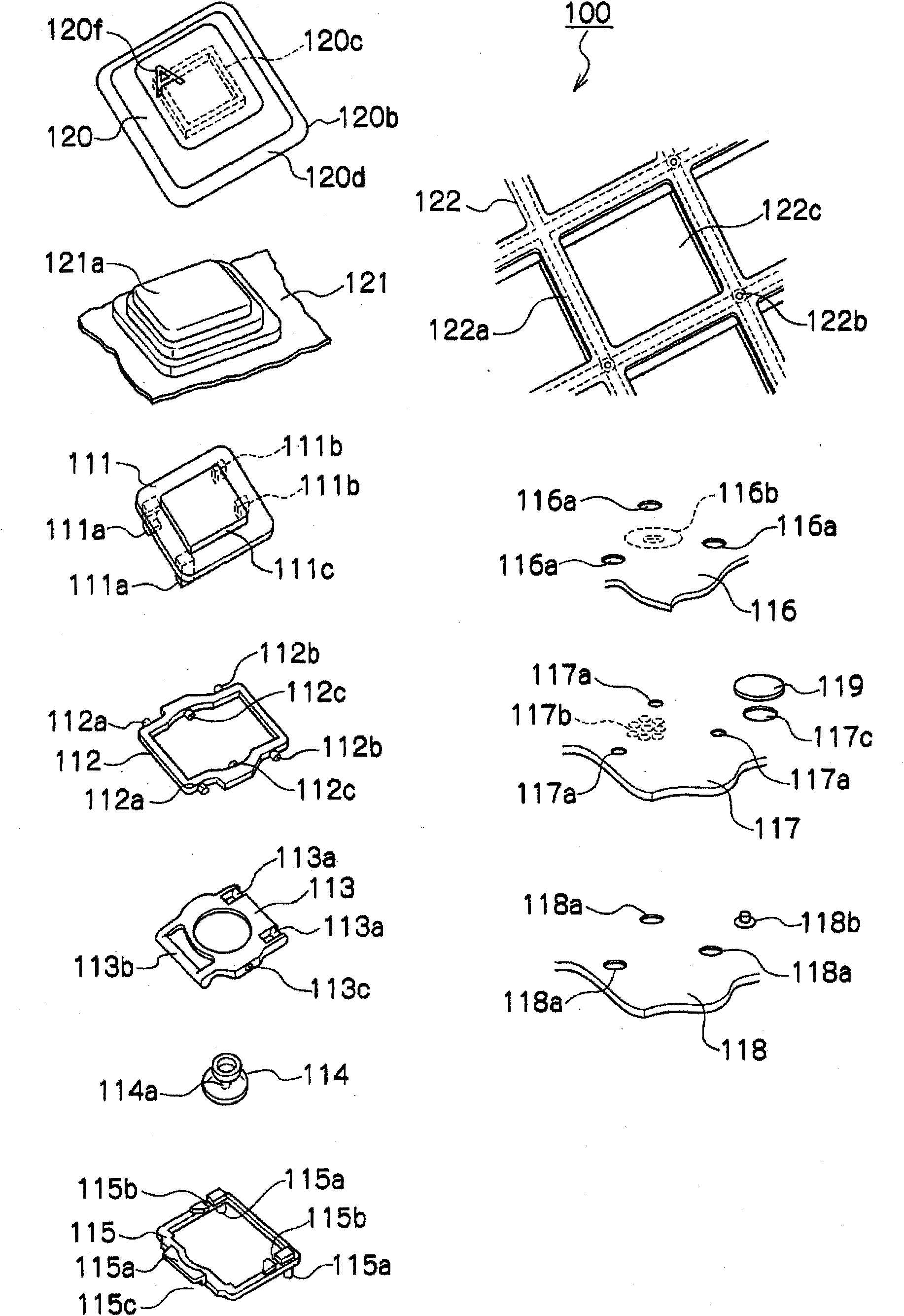
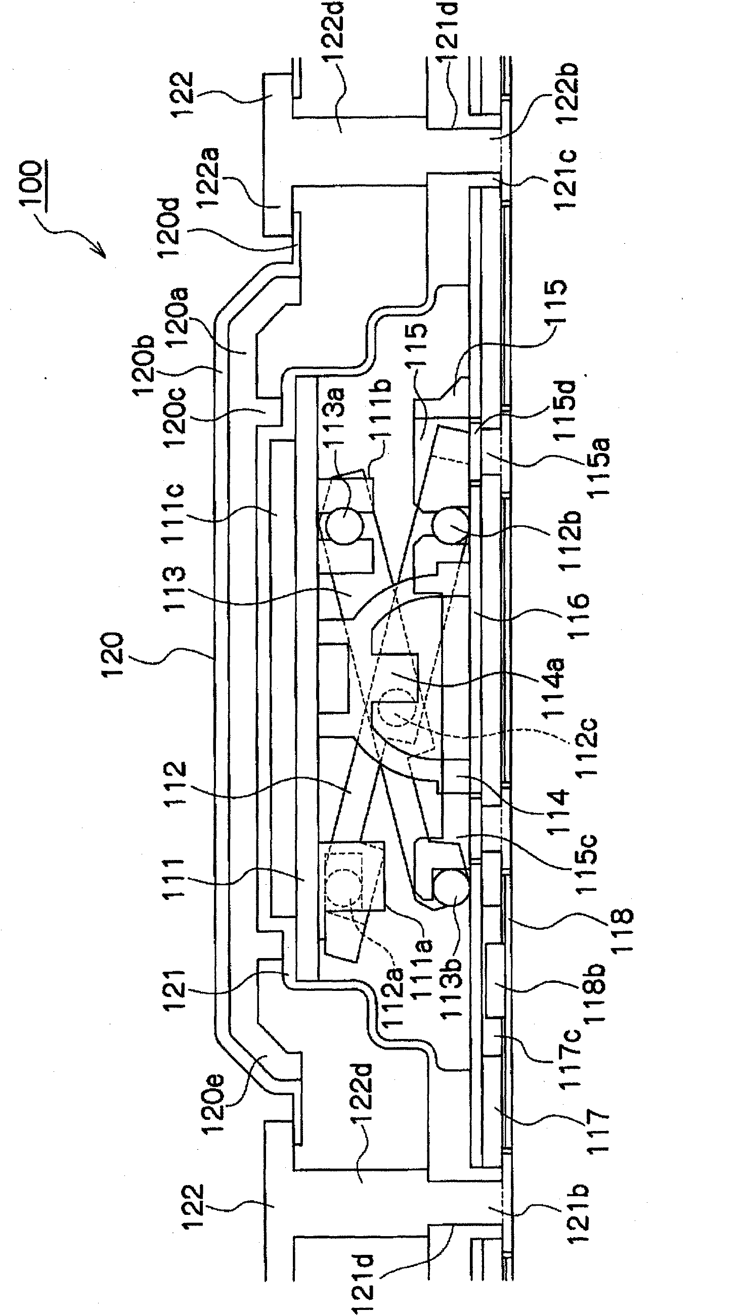
[0052] The key pressing operation of the second embodiment is the same as the operation of the above-mentioned first embodiment, so the description thereof will be omitted. Here, the lighting operation in Example 2 will be described. exist Figure 10 In this case, when the LED 218b is turned on by a power source not shown, the light emitted from the LED 218b passes through the inside of the back plate 217 having a light guiding function. A reflective sheet 219 is provided under the LED 218b, so that the light emitted from the LED 218b does not leak downward, but is reflected by the reflective sheet 219 and passes through the inside of the back plate 217 . Furthermore, since the LED sheet 218 or the diaphragm 216 has a reflective function on the upper part of the back plate 217 , the light emitted from the LED 218 b passes through the inside of the back plate 217 without leaking upward. The light is reflected by the reflective portion 217 b provided at a position correspondin...
Embodiment 3
[0059] The assembly operation and lighting operation in Example 3 are the same as those in the first embodiment. According to Embodiment 3, in addition to the effect of Embodiment 1 above, by providing a boss portion 317d on the back plate 317 having a light guiding function, the welded front end portion of the welding pin 315a of the bracket 315 is inserted into the boss. Therefore, the welded portion does not protrude downward of the back plate 317 . Since it is not necessary to provide holes in the LED sheet 318, waterproofness can also be ensured.
[0060] Next, Example 4 of the present invention will be described. Figure 14 It is an exploded perspective view showing the keyboard structure of Embodiment 4, Figure 15 It is a sectional view showing the structure of the keyboard of the fourth embodiment. exist Figure 14 , Figure 15 In the key switch 400 of Embodiment 4, the key top 420, the sheet-shaped elastic part 421, the movable plate 411, the first link part 412...
Embodiment 4
[0063] The assembly operation and lighting operation in Example 4 are the same as in Example 2. According to Embodiment 4, in addition to the effects of Embodiment 2 described above, by providing the boss portion 417d on the back plate 417, the welded front end portion of the welding pin 415a is inserted into the inside of the boss portion 417d, thereby welding The bottom part will not protrude to the bottom of the back plate 417. Since it is not necessary to provide holes in the reflection sheet 419, waterproofness can also be ensured.
[0064] The present invention is not limited to the above-described embodiments, and various modifications can be made. For example, in the above-mentioned Embodiment 2 and Embodiment 4, the LED chips 218, 418 are disposed under the diaphragms 216, 416, but the diaphragm 216 may be disposed under the LED chips 218, 418 conversely. , 416 structures. At this time, holes in which LEDs are embedded are provided in the diaphragms 216 and 416 . ...
PUM
 Abstract
Description
Claims
Application Information
 - R&D
- Intellectual Property
- Life Sciences
- Materials
- Tech Scout
- Unparalleled Data Quality
- Higher Quality Content
- 60% Fewer Hallucinations
Browse by: Latest US Patents, China's latest patents, Technical Efficacy Thesaurus, Application Domain, Technology Topic, Popular Technical Reports.
© 2025 PatSnap. All rights reserved.Legal|Privacy policy|Modern Slavery Act Transparency Statement|Sitemap|About US| Contact US: help@patsnap.com


