Supercharge Your Innovation With Domain-Expert AI Agents!

Air landing device

A descender and component technology, applied in life-saving equipment, building rescue, etc., can solve problems such as uneven force, unreasonable crankshaft force structure, and undisclosed rope winding technology

Inactive Publication Date: 2012-07-25
何少敦
View PDF0 Cites 0 Cited by
  • Summary
  • Abstract
  • Description
  • Claims
  • Application Information

AI Technical Summary

Problems solved by technology

[0003] In order to overcome the disadvantages of unreasonable crankshaft stress structure and undisclosed rope rewinding technology in the current air landing devices that use crankshafts and speed-limiting pistons, which cause potential danger and inconvenience to users, the present invention proposes an air landing device. The principle is: set a synchronously rotating rotating assembly on both sides of the rope winding disk, the crankshaft is installed between the rotating parts of the synchronous rotating assembly, thus solving the problem of uneven force, and by setting a one-way rotating member, when the rope Under the action of gravity, the rope is driven to rotate around the coil in one direction and drive the crankshaft to rotate. When the crankshaft rotates, it drives the hydraulic speed limiting assembly to act, but when the rope rotates in the opposite direction, the crankshaft does not rotate, and the hydraulic speed limiting assembly does not operate. Solve the rope looping

Method used


Image

  • Air landing device
  • Air landing device
  • Air landing device

Examples


Embodiment Construction

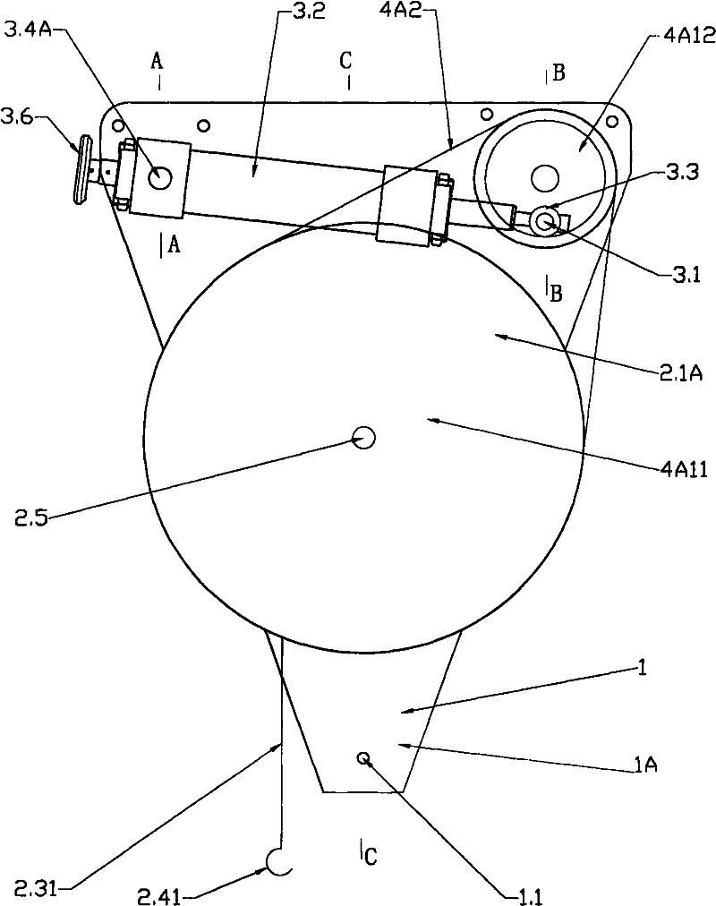
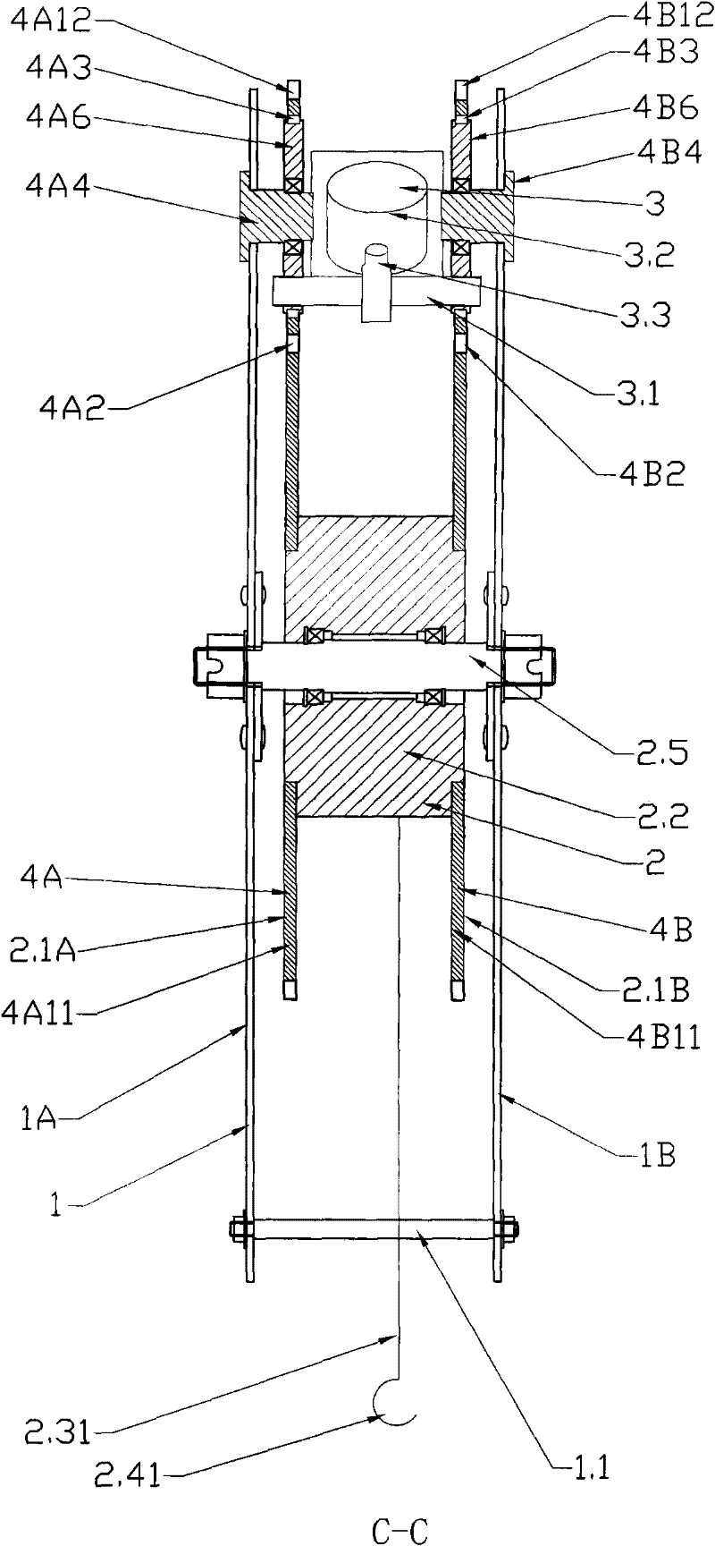
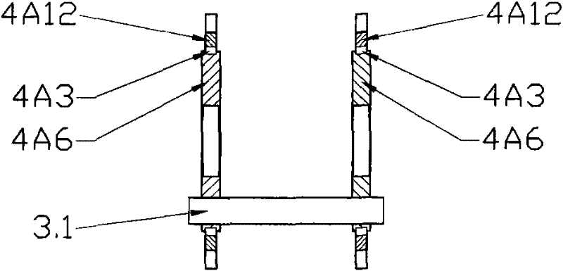
[0053] Figure 1 to Figure 5 It is a structural schematic diagram of the first embodiment of the present invention, figure 1 main view, figure 2 It is the C-C sectional view of this embodiment, image 3 for the partial view, Figure 4 It is the B-B sectional view of this embodiment, Figure 5 It is the A-A sectional view of this embodiment.

[0054] exist Figure 1 to Figure 5It can be seen from the figure that in this implementation, the descender mainly includes a body 1, a rope winding assembly 2, and a hydraulic speed limiting assembly 3; the body 1 mainly includes supports 1A and 1B; the rope winding assembly 2 mainly includes windings 2.1A and 2.1 B. Central piece 2.2, rope 2.31, rope end fixing part 2.41 and central shaft 2.5, rope 2.31 is wound on the rope reel and a rope end fixing part 2.41 is set at the end, and the reel is installed on supports 1A and 1B through central shaft 2.5 Above; the hydraulic speed limiting assembly 3 mainly includes the crankshaft 3....


PUM


Abstract

The invention provides an air landing device, in order to overcome the defects of potential dangers and inconvenient use for users due to that the conventional air landing device with a crank and a speed-limiting piston is an unreasonable crank stress structure and does not disclose a rope recoiling technology. The air landing device is characterized in that rotating components which synchronously rotate are arranged on two sides of a rope coiling disc; a crank is arranged between the rotating parts of the synchronous rotating components to solve the problem of uneven stress; a one-way rotating component is arranged, thus a hydraulic speed-limiting component is driven to act when a rope drives the rope coiling disc to rotate toward one direction and drives the crank to rotate under the action of gravity; the hydraulic speed-limiting component is driven to act when the crank rotates; and the crank does not rotate when the rope coiling disc rotates in an opposite direction, and the hydraulic speed-limiting component does not act, so that the rope is prevented from rewinding.

Description

technical field [0001] The invention relates to a landing device, in particular to a hydraulic speed-limiting aerial descender. Background technique [0002] In daily life or work, people often encounter danger at high places. If there is no other way to escape, they need to escape by means of air landing devices. Known air landing devices include friction speed limiting, manual braking speed limiting and Hydraulic damping speed-limiting type, the first two disadvantages are poor reliability, the last one is relatively simple in structure, and its performance is also relatively reliable. CN87216143 discloses a kind of air landing device that uses a piston and a cam to limit the speed, but the cam only bears pressure and does not bear pressure. Pull force, there is uneven speed limit during the landing process; ZL2003101127389 and ZL2003201232361 respectively disclose a principle of connecting the crankshaft with a hydraulic speed-regulating controller, but due to the use of ...

Claims


Application Information

Patent Timeline
Patent Type & Authority Patents(China)
IPC IPC(8): A62B1/12
CPCA62B1/12
Inventor 何少敦
Owner 何少敦
Features
  • R&D
  • Intellectual Property
  • Life Sciences
  • Materials
  • Tech Scout
  • Unparalleled Data Quality
  • Higher Quality Content
  • 60% Fewer Hallucinations
Learn More