
Method for forming spigot end of large-diameter socket and spigot type reinforcement concrete pipe

A molding method and socket-type technology, which is applied in reinforced molding, ceramic molding machines, manufacturing tools, etc., can solve the problems of easy deformation of semi-circular molds, lower precision of sockets and sockets, unusable molds, etc., and achieve the effect of improving molding accuracy

Active Publication Date: 2012-05-23
SHANGHAI URBAN CONSTRUCTION MUNICIPAL ENGINEERING (GROUP) CO LTD
View PDF0 Cites 0 Cited by
  • Summary
  • Abstract
  • Description
  • Claims
  • Application Information

AI Technical Summary

Problems solved by technology

But it is unavoidable that since it is a full circle composed of two semicircles, the accuracy is low, and the accuracy of the water stop groove at the socket end is difficult to guarantee, and the semicircle mold is easily deformed after repeated disassembly and assembly.
Because the precision requirements of the reinforced concrete pipe body are not high, it is not economical to increase the production requirements of the entire mold in order to ensure the precision of the water stop groove at the spigot end, and no matter how the precision is improved, the defect that the semicircular mold is easy to deform still exists, resulting in bearing, The accuracy of the socket is reduced, and the mold cannot be used
[0004] The above disadvantages are not obvious in the small-diameter reinforced concrete pipe, but for the large-diameter socket-type reinforced concrete pipe, it is difficult to meet the forming accuracy requirements with the existing mold form

Method used


Image

  • Method for forming spigot end of large-diameter socket and spigot type reinforcement concrete pipe
  • Method for forming spigot end of large-diameter socket and spigot type reinforcement concrete pipe
  • Method for forming spigot end of large-diameter socket and spigot type reinforcement concrete pipe

Examples


Embodiment Construction

[0024] The features of the present invention and other related features will be further described in detail below in conjunction with the accompanying drawings through embodiments, so as to facilitate the understanding of those skilled in the art:

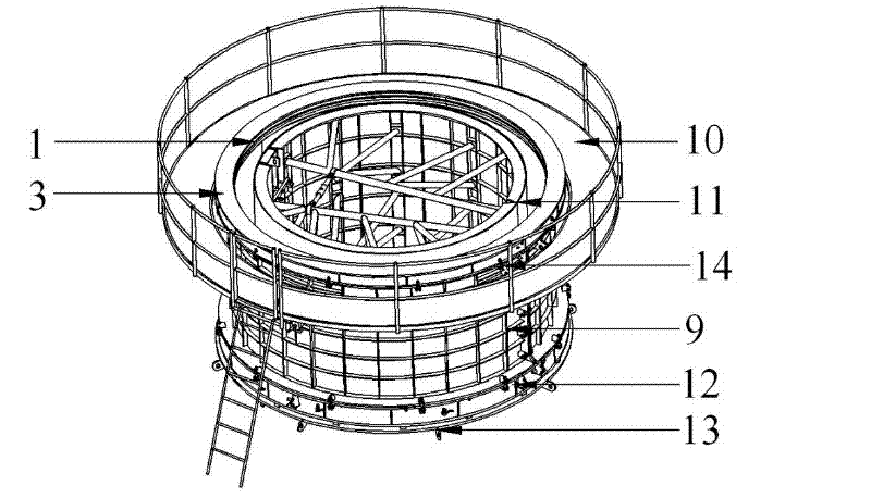
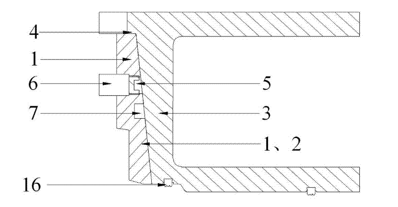
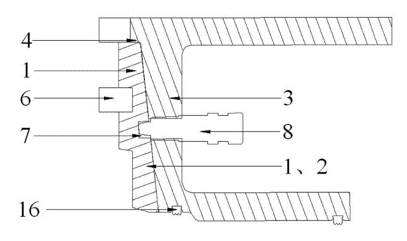
[0025] Such as Figure 1 to Figure 4 As shown, the total reference numerals 1-16 represent respectively: forming mold 1, half mold 2, positioning mold 3, flange 4, screw hole 5, steel ring 6, groove 7, clip 8, middle mold 9, working platform 10. Inner mold 11, lower mold 12, bottom mold 13, closing bolt 14, positioning pin 15, rubber ring 16.

[0026] see figure 1 As shown, the reinforced concrete pipe mold adopted in the present invention is mainly composed of bottom mold 13, lower mold 12, middle mold 9, upper mold and inner mold 11, wherein the upper mold is a pouring mold for the outer surface of the socket end, and the middle mold 9 is the casting mold for the outer surface of the reinforced concrete pipe body, the lower mol...


PUM


Abstract

The invention relates to the technical field of concrete pipe joint moulds, and particularly relates to a method for forming a spigot end of a large-diameter socket and spigot type reinforcement concrete pipe. The method comprises the following steps: splicing two semi-modules in the same shape to form a forming mould for limiting the appearance of the spigot end during pouring, wherein a cylinder-like cavity is formed inside the forming mould, and the outside of the forming mould is like a cone; sleeving a positioning mould on the forming mould, wherein a conical cavity matched with the conical degree of the appearance of the forming mould is formed in the positioning mould; connecting the positioning mould with the forming mould, and hanging the positioning mould and the forming mould to the upper end of a medium mould; coaxially and fixedly connecting the positioning mould with the medium mould; assembling a steel ring in the cavity of the forming mould, assembling a steel reinforcement cage frame of the reinforcement concrete pipe, and fixedly connecting the steel reinforcement cage frame with the steel ring; and assembling an inner mould, and pouring a concrete structure. The method has the advantages that the forming accuracy of the spigot end of a super-large-diameter reinforced concrete pipe is improved, and the accuracy of the steel mould structure cannot be reduced under the condition of repeated assembly and disassembly.

Description

technical field [0001] The invention relates to the technical field of concrete pipe joint molds, in particular to a method for forming the socket end of a large-diameter socket-type reinforced concrete pipe. Background technique [0002] Concrete pipes are widely used in jacking construction, and are generally used in areas where it is difficult to slot, have high requirements for the construction environment, and cannot cause ground subsidence under specific geographical conditions, such as railways, highways, etc. Underground construction under objects. At present, the main structure of reinforced concrete pipes used in jacking method construction is: a steel cage is embedded in the concrete pipe wall, and the steel cage is assembled by two coaxial cylindrical steel skeletons through erecting steel bars. One end of the wall is fixed with a steel collar as a socket, and the other end of the concrete pipe wall is grooved outside as a socket, and the connection between the ...

Claims


Application Information

Patent Timeline
IPC IPC(8): B28B21/02B28B21/56
Inventor 居贤镛桂植梁张开寅陈立生葛金科沈君华
Owner SHANGHAI URBAN CONSTRUCTION MUNICIPAL ENGINEERING (GROUP) CO LTD
Learn More