Main brake valve with electronic-control pneumatic-control dual-circuit signals

A brake master valve, dual-circuit technology, applied in the direction of control valve and bleed valve, brake, brake components, etc., can solve dangerous accidents, brake system can not effectively control brake line pressure changes, vehicle braking and other issues to achieve high security

Active Publication Date: 2013-05-01
RUILI GROUP RUIAN AUTO PARTS CO LTD
View PDF0 Cites 3 Cited by
  • Summary
  • Abstract
  • Description
  • Claims
  • Application Information

AI Technical Summary

Problems solved by technology

Therefore, often when the brake pedal sensor fails or a transmission failure occurs during the transmission of a separate electrical signal or air pressure signal, the brake system cannot effectively control the pressure change of the brake line to perform vehicle braking. so prone to dangerous accidents

Method used


Image

  • Main brake valve with electronic-control pneumatic-control dual-circuit signals
  • Main brake valve with electronic-control pneumatic-control dual-circuit signals
  • Main brake valve with electronic-control pneumatic-control dual-circuit signals

Examples


Embodiment Construction

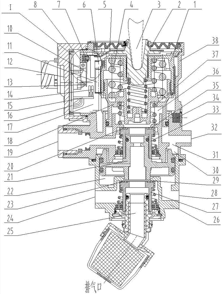
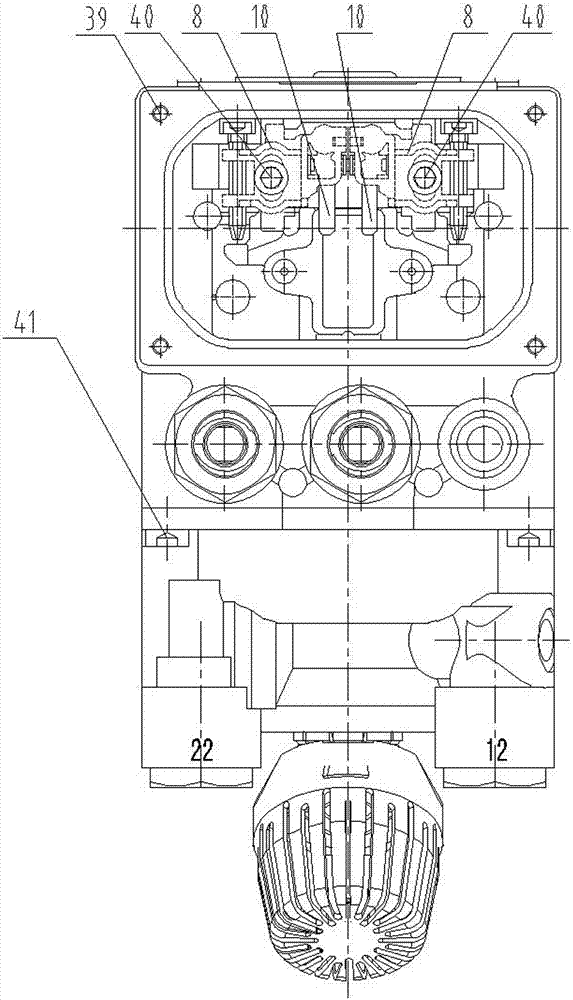
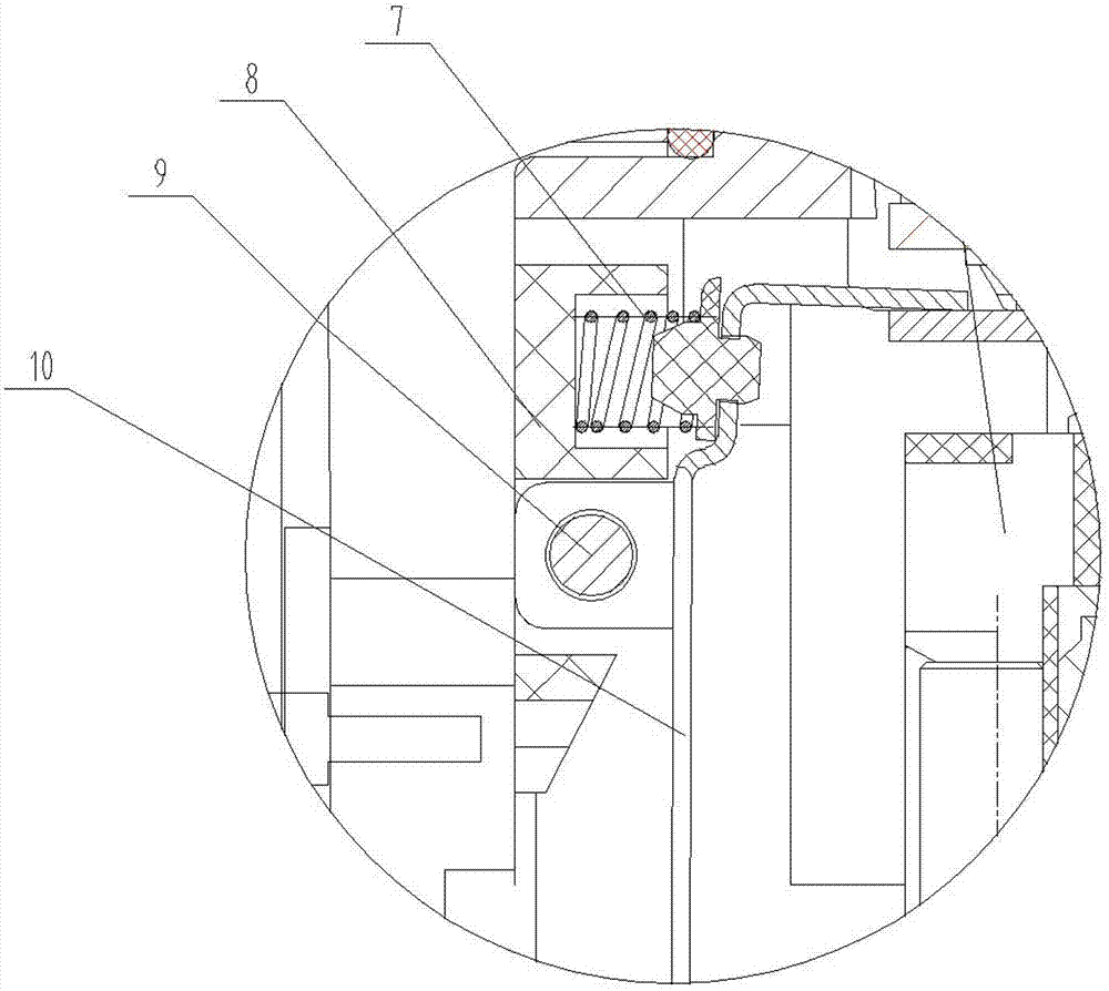
[0061] like Figure 1-4 As shown, the present invention relates to a brake master valve with an electric control double circuit and a pneumatic control double circuit. 38. The lower valve body 26 is connected by the bolt 41, the plug seat 12 is connected with the upper valve body 26 by the bolt 39; the ejector rod seat 2 of the brake master valve is connected with the brake pedal through the ejector rod 3; : upper piston 1, ejector rod seat 2, balance spring 4, upper valve 33, etc.; baffle plate 5 and ejector rod seat 2 are fixed together by riveting or welding; electromagnetic core seat 6 is fixed on the outer ring of upper piston 1, The electromagnetic core 11 is fixed on the electromagnetic core seat 6, the middle piston 18 and the balance spring 4 are placed in the upper piston 1; the upper valve body is also provided with a filter plug 34, and the air chamber 17 is the same as the atmosphere through the filter plug, so that the upper piston 1. The lower piston 21 and oth...


PUM


Abstract

The invention relates to a main brake valve with electronic control and pneumatic control, which is characterized in that dual-circuit electronic control and dual-circuit pneumatic control are generated respectively by electrical signals and pneumatic signals which are obtained through detecting a brake intent, thereby controlling the rise and drop of brake pressure of a brake system, wherein twocontrol circuits independently exist in the main brake valve, when one of the control circuits malfunctions, the other control circuit keeps running; and when one circuit in the dual-circuit control malfunctions, the other circuit still takes effect. By using the main brake valve provided by the invention, braking operations implemented by drivers become safer and more reliable.

Description

technical field [0001] The invention relates to a brake master valve with both electric control and gas control, and is especially applied to an electronically controlled braking system (referred to as an EBS system) and a braking system of a new energy vehicle. The invention belongs to the technical field of automobile braking system control. Background technique [0002] Air pressure-controlled dynamic braking systems are widely used in commercial vehicles such as trucks and buses. Usually, air compressors and high-pressure gas storage cylinders are used to supply air. The driver operates the brake master valve to control the air pressure in the brake pipeline. Air is sent to the pistons in the wheel braking system, which causes the air brakes to generate the corresponding braking force. The main brake valve of the car is an important structure in the braking system. When the car brakes, the air pressure delivered to each brake cavity through the main brake valve, the for...

Claims


Application Information

Patent Timeline
Patent Type & Authority Patents(China)
IPC IPC(8): B60T15/04
Inventor 李传武杨柳冯跃刘昕
Owner RUILI GROUP RUIAN AUTO PARTS CO LTD
Why Eureka
Try Eureka