[0027] Example 1
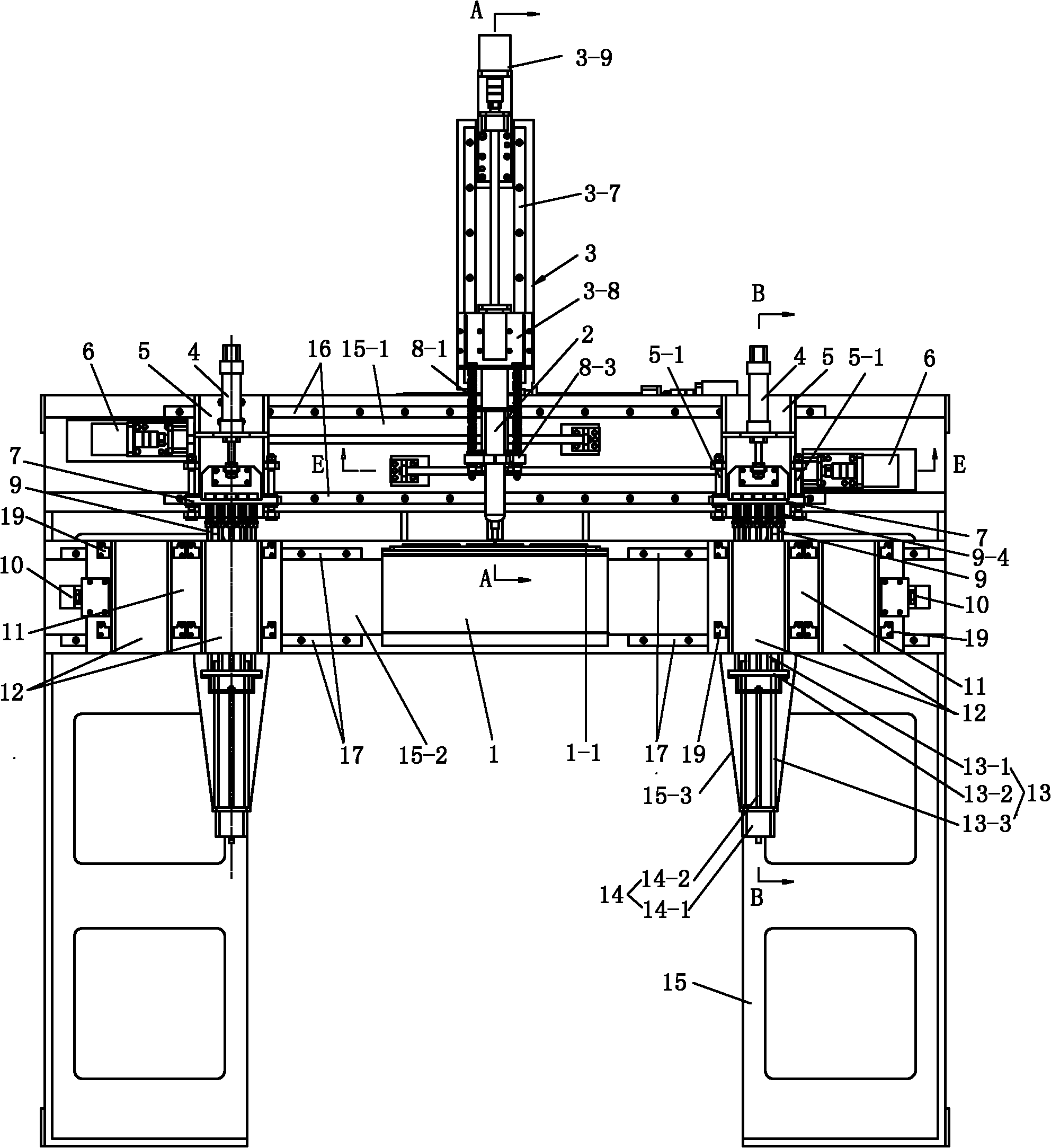
[0028] see Figure 1 to Figure 4 , The automatic dispensing and placement machine shown includes a frame 15. The frame 15 has upper and lower front walls 15-1 and 15-2. The lower front wall 15-2 of the frame is fixed with a workbench 1, a workbench 1. There is a numerical control system operation panel 1-1, and a glue dispensing device supported by the frame 15 is arranged above the workbench 1. The glue dispensing device includes a glue cylinder 2, a glue cylinder 2 that drives the glue cylinder 2 to move three-dimensionally relative to the workbench 1 The device 3 and the dispensing volume control assembly connected with the glue cylinder 2.
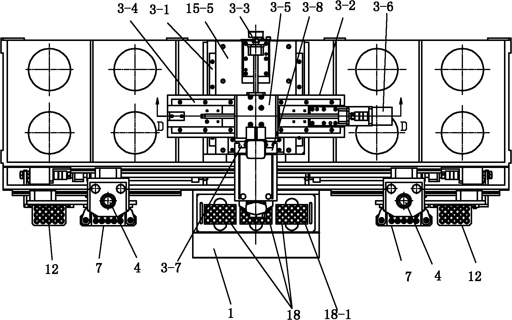
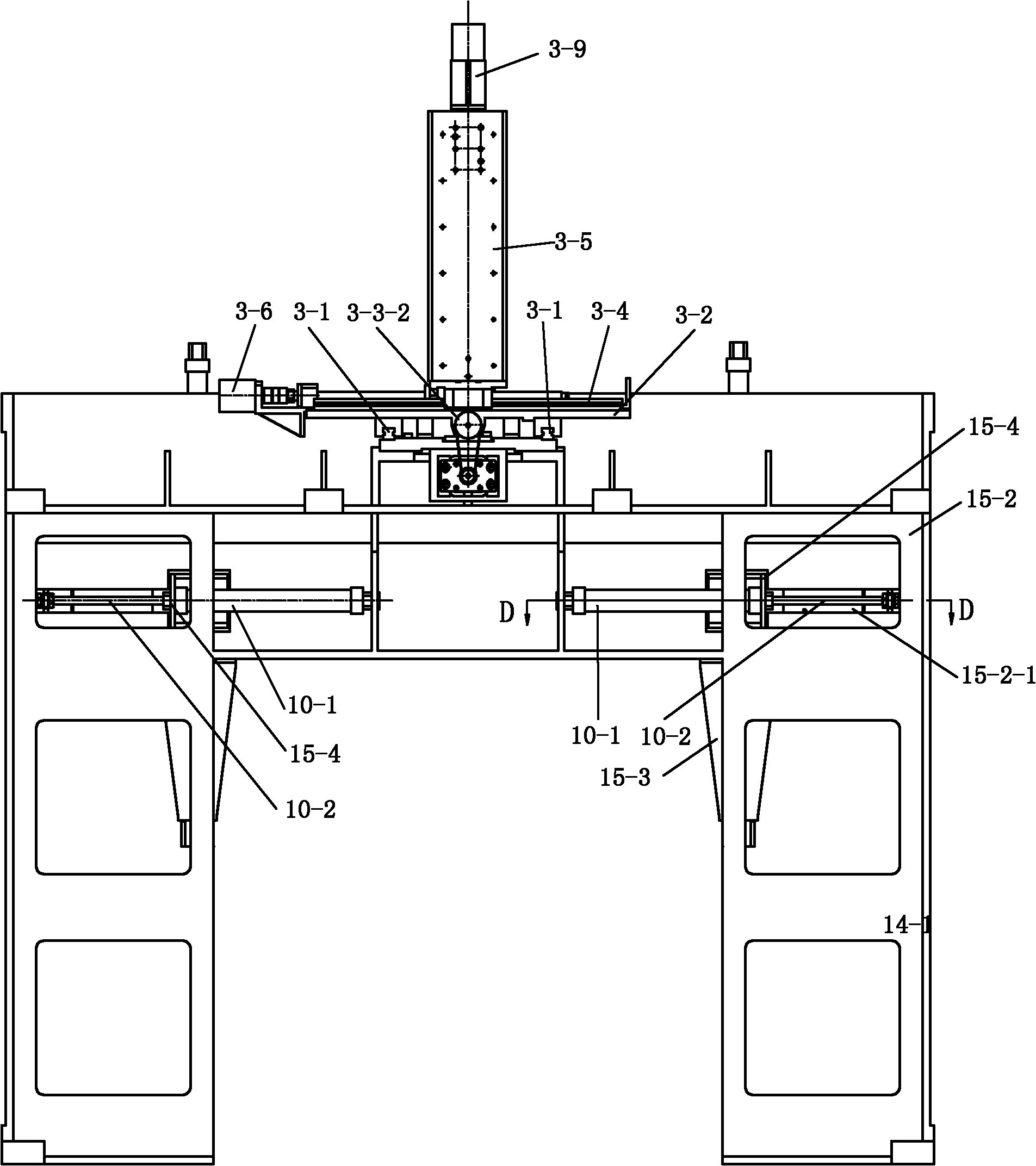
[0029] see Figure 1 to Figure 5 , Figure 8 , The dispensing driving device 3 includes a front and rear dispensing guide 3-1, a sliding bottom plate 3-2, a front and rear dispensing driving mechanism 3-3, a left and right dispensing guide 3-4, a sliding post 3-5, left and right Dispensing drive mechanism 3-6, up and down dispensing guide 3-7, sliding glue barrel rack 3-8, and up and down dispensing drive mechanism 3-9.
[0030] The front and rear dispensing guide 3-1 is fixed on the top of the rack 15-5, and the front and rear dispensing drive mechanism 3-3 includes a No. 1 stepping motor 3-3-1 and a No. 1 ball forming a rotating pair Screw 3-3-4 and No. 1 screw nut 3-3-5, the No. 1 stepping motor 3-3-1 is fixed on the back of the frame, and the No. 1 ball screw 3-3-4 is The No. 1 bearing seat 3-3-3 fixed on the top surface of the frame 15-5 is supported, and the No. 1 bearing seat 3-3-3 is equipped with two angular contact ball bearings. The No. 1 stepping motor is connected to the No. 1 ball screw 3-3-4 through the belt drive mechanism 3-3-2. The No. 1 ball screw 3-3-4 is equipped with a gland 3-3-6 and a spacer. 3-3-7 and lock nut 3-3-8, gland 3-6-6 lock the bearing outer ring, spacer 3-6-7 and lock nut 3-6-8 lock the bearing inner ring. The sliding bottom plate 3-2 is connected to the No. 1 screw nut 3-3-5. When the No. 1 stepping motor 3-3-1 rotates through the belt drive mechanism 3-3-2 to drive the No. 1 ball screw 3-3-4 to rotate, so that the No. 1 screw nut 3-3-5 is in the No. 1 ball screw. The rod 3-3-4 is moved axially, thereby driving the sliding bottom plate 3-2 to move forward and backward on the dispensing guide 3-1.
[0031] The left-right dispensing guide 3-4 is fixed on the sliding bottom plate 3-2, and the left-right dispensing drive mechanism 3-6 includes a No. 2 stepping motor 3-6-1 and a No. 2 rotating pair. The ball screw 3-6-4 and the No. 2 screw nut 3-6-5, the No. 2 stepping motor 3-6-1 is fixed on the sliding base plate 3-2, the No. 2 ball screw 3-6-4 is supported by the No. 2 bearing seat 3-6-3 fixed on the sliding base plate 3-2, and the No. 2 bearing seat 3-6-3 is equipped with two angular contact ball bearings. The No. 2 stepping motor 3-6-1 is connected with the No. 2 ball screw 3-6-4 through the No. 2 coupling 3-6-2, and the No. 2 ball screw 3-6-4 is equipped with a gland 3 -6-6, spacer 3-6-7 and lock nut 3-6-8, gland 3-6-6 locks the bearing outer ring, spacer 3-6-7 and lock nut 3-6 8 Lock the inner ring of the bearing. The sliding post 3-5 is connected to the No. 2 screw nut 3-6-5, and the sliding post 3-5 is driven by the No. 2 screw nut 3-6-5 to move on the left-right dispensing guide 3-4.
[0032] The vertical dispensing guide 3-7 is fixed on the front surface of the sliding column 3-5, and the vertical dispensing driving mechanism 3-9 includes a No. 3 stepping motor 3-9-1 and a rotating pair 3 No. 3 ball screw 3-9-4 and No. 3 screw nut 3-9-5, No. 3 stepping motor 3-9-1 fixed on the sliding column 3-5, No. 3 ball screw 3-9-4 Supported by the No. 3 bearing seat 3-9-3 fixed on the sliding column 3-5, there are two angular contact ball bearings in the No. 3 bearing seat 3-9-3. No. 3 stepping motor 3-9-1 is connected with No. 3 ball screw 3-9-4 through No. 3 coupling 3-9-2, and No. 3 ball screw 3-9-4 is also equipped with a gland 3 -9-6, spacer 3-9-7 and lock nut 3-9-8. The sliding rubber barrel holder 3-8 is connected to the No. 3 screw nut 3-9-5, and the sliding rubber barrel holder 3-8 is driven by the No. 3 screw nut 3-9-5 on the up and down dispensing guide 3- 7 on the move.
[0033] The glue cylinder 2 is connected to the sliding glue cylinder holder 3-8 through a buffer device 8. The buffer device 8 includes a buffer rod 8-1, a buffer spring 8-2, a rubber collet 8-3, a linear bearing 8-4 and a spacer 8-5 arranged on the buffer rod 8-1 from top to bottom, The rubber tube 2 is provided with a rubber tube holder 8-6, the buffer rod 8-1 is fixed on the sliding rubber tube holder 3-8, and the rubber tube 2 is connected to the rubber tube holder 8-6 On the above-mentioned collet 8-3. When the glue cylinder 2 receives a large reaction force during glue dispensing, the buffer spring 8-2 absorbs the reaction force and protects the glue nozzle of the glue cylinder. The setting of the glue cylinder holder 8-6 ensures that the glue cylinder is always In a vertical position.
[0034] The dispensing amount control assembly includes an air pump (illustration omitted), and the air pump is connected to the top air intake pipe 2-1 of the glue cylinder 2 by a hose.
[0035] see Figure 1 to Figure 4 , Image 6 , Figure 7 with Picture 9 , The two sides of the glue dispensing device are respectively provided with manipulator devices. A pair of left-right upper guide rails 16 are fixed on the upper front wall 15-1 of the frame 15. Each of the two manipulator devices includes an upper sliding seat 5 arranged on the upper guide rail 16, and driving the upper sliding seat 5 on the upper guide rail. 16 an upper sliding seat driving mechanism 6 sliding left and right, a straw seat driving mechanism 4 provided on the upper sliding seat 5, and a straw seat 7 driven by the straw seat driving mechanism 4 to move up and down. Two guide rods 5-1 are provided on the upper sliding base 5, and the straw base 7 moves up and down along the two guide rods 5-1.
[0036] The upper sliding seat driving mechanism 6 includes a No. 4 stepping motor 6-1 and a No. 4 ball screw 6-4 and a No. 4 screw nut 6-5 that form a screw pair. The No. 4 stepping motor 6-1 Fixed on the front wall 15-1 of the frame, the No. 4 ball screw 6-4 is supported by the No. 4 bearing seat 6-3 and No. 5 bearing seat 6-9 fixed on the front wall 15-1 of the frame, No. 4 bearing seat 6-3 is equipped with two angular contact ball bearings, and No. 5 bearing seat 6-9 is provided with a radial ball bearing. The No. 4 stepping motor 6-1 is connected to the No. 4 ball screw through the No. 4 coupling 6-2. The No. 4 ball screw 6-4 also has a gland 6-6, a spacer 6-7 and a lock Nuts 6-8. The upper sliding seat 5 is connected to the No. 4 screw nut 6-5, and the upper sliding seat 5 is driven by the No. 4 screw nut 6-5 to move on the No. 4 ball screw 6-4.
[0037] The straw seat driving mechanism 4 includes a straw seat cylinder, the straw seat cylinder cylinder 4-1 is fixed on the upper sliding seat 5, and the straw seat 7 is connected to the piston rod 4-2 of the straw seat cylinder. The straw holder 7 is driven by the upper sliding seat driving mechanism 6 and the straw holder driving mechanism 4 to move left and right and up and down.
[0038] The straw holder 7 is provided with straw holes 7-1 arranged in a 5×3 matrix, and each straw hole 7-1 is provided with a vacuum straw 9, and each vacuum straw 9 is connected with a suction cup 9-1 at the lower end, and the top is connected There is a vacuum connector 9-2, each vacuum suction pipe 9 is connected to a vacuum pump (not shown) through a vacuum connector 9-2, and each vacuum suction pipe 9 is threadedly connected to the position where the suction pipe seat 7 extends downwards as a stopper. 9-3. A compression spring 9-4 is provided on the vacuum suction tube 9 between the suction tube base 7 and the nut 9-3, and the compression spring 9-4 exerts a downward force on the vacuum suction tube 9.
[0039] A pair of left-right lower guide rails 17 are fixed on the lower front wall 15-2 of the frame and on both sides of the workbench 1. Each lower guide rail 17 is provided with a lower sliding seat 11, each lower sliding seat 11 There are two bins 12, each bin 12 is hung on four bin positioning parts 19, the bins 12 can be easily exchanged, one of the bins 12 is located at the working position, and the other is used as a spare Material box. Each lower sliding seat 11 is driven by the lower sliding seat driving mechanism 10 to slide left and right on the corresponding lower guide rail 17. The lower sliding seat driving mechanism 10 includes a lower sliding seat cylinder. The lower sliding seat cylinder 10-1 is fixed on the bracket 15-4 on the back of the lower front wall 15-2, and the lower front wall 15-2 is provided with an exposed lower slide The groove 15-2-1 of the cylinder piston rod 10-2 is seated, and the connecting portion 11-1 of the lower sliding seat 11 is connected to the piston rod 10-2 of the cylinder through the groove 15-2-1.
[0040] Each material box 12 has a material storage cavity 12-1 arranged in the same matrix as the vacuum suction tube 9 on the suction tube base 7, and the vacuum suction tube 9 can be inserted into the material storage cavity 12-1 of the material box 12.
[0041] At the lower part of the lower front wall 15-2 of the frame and below the working position of the material box, there are respectively lower brackets 15-3. Each lower bracket 15-3 is equipped with a lifting device to ensure that the substrates in the material box are in the same The height or the patch in the bin are all at the same height. The ejector device includes a jack assembly 13 and a jack drive mechanism 14. The jack assembly 13 includes a jack seat 13-2, a jack 13-1 connected to the jack seat 13-2, and a lower bracket 15- The two guide rods 13-3 on 3, the top rod seat 13-2 and the two guide rods 13-3 are movably connected, and the top rod seat 13-2 moves up and down along the guide rod 13-3. The arrangement of the ejector rod 13-1 is the same as the matrix arrangement of the storage cavity 12-1 of the material box 12. At the bottom of the material box 12 corresponding to the center of each storage cavity 12-1 is provided an ejector rod hole 12-2. The rod 13-1 is inserted into the storage cavity 12-1 through the ejector hole 12-2 of the material box 12. The jack drive mechanism 14 includes a linear stepping motor 14-1, the linear stepping motor 14-1 is fixed on the lower bracket 15-3, and the jack seat 13 is connected to the linear stepping motor 14-1 On the extension shaft 14-2. Each time a piece of material in the material box is removed, the linear stepping motor receives the rotation signal and drives the ejector base 13-2 to move up, and lifts the following material up a certain distance to ensure that the height of the captured material is not change.
[0042] see figure 1 , figure 2 with Figure 5 , The operation panel 1-1 of the workbench 1 is provided with three box molds 18 arranged left and right, and each box mold 18 is provided with mold cavities 18-1 arranged in the same matrix as the vacuum straws 9 on the straw base 7 .
[0043] The ejector rod driving mechanism 14 can also adopt an air cylinder (refer to figure 1 ), the mandrel cylinder block is fixed on the lower bracket 15-3, and the mandrel seat 13 is connected to the elongated piston rod of the mandrel cylinder.
[0044] The dispensing and placement machine is controlled by a numerical control system. It has three stations. The process is divided into three steps. The first step is to grab the substrate at the first station and send it to the second station, namely the dispensing station. The first step is to dispense glue, and the third step is to grab the patch at the third station and send it to the dispensing station, and press the patch on the substrate. The substrate and the patch are pre-packed into the material box, and the material box full of the substrate and the patch is placed on the lower sliding seat 11 of the two manipulator devices at the first and third stations, respectively. The suction pipe seat driving mechanism 4 of the robot device of the first station drives the vacuum suction pipe 9 into the corresponding material box 12. The vacuum suction pipe 9 is always attached to the top surface of the corresponding storage cavity in the material box 12 under the action of the compression spring 8. This embodiment sucks 15 substrates at a time. The suction pipe 9 is driven by the suction pipe holder driving mechanism 4 to pick up the substrate, and the upper sliding seat 5 drives the vacuum suction pipe 9 to move to the second station. After being placed in the cavity of one of the box molds 18 at one time, the upper sliding seat 5 of the manipulator device at the first station returns to the first station to continue to grasp the substrate, and the glue cylinder of the dispensing device at the second station Driven by the dispensing drive device 3, the 15 substrates are dispense in sequence. At the same time, the vacuum suction pipe 9 of the robot device in the third station completes the pick and place. After the dispensing is completed, the robot in the third station The device moves the patch to the second station through the movement of the upper sliding seat and places it on the substrate. After being compressed for a certain period of time, the upper sliding seat 5 of the manipulator device at the second station returns to the third station. Repeat the above actions to operate the second box mold, and at the same time, the operator removes the box mold that has finished dispensing, replaces the empty box mold, and so on. There are two bins. When one bin is empty, the lower sliding seat 11 drives the other full-load bin to move to the working position, so as to achieve continuous operation without stopping the machine.