Touch control display device

A touch display device, touch panel technology, applied in static indicators, optics, instruments, etc., can solve the problems of increasing the number of parts, increasing the thickness of products, and unfavorable product manufacturing.

Active Publication Date: 2011-07-13
AU OPTRONICS CORP
View PDF3 Cites 16 Cited by
  • Summary
  • Abstract
  • Description
  • Claims
  • Application Information

AI Technical Summary

Problems solved by technology

However, this method will not only increase the thickness of the product, but also increase the number of parts required in a single product, which is not conducive to the production of the product

Method used


Image

  • Touch control display device
  • Touch control display device
  • Touch control display device

Examples


no. 1 example

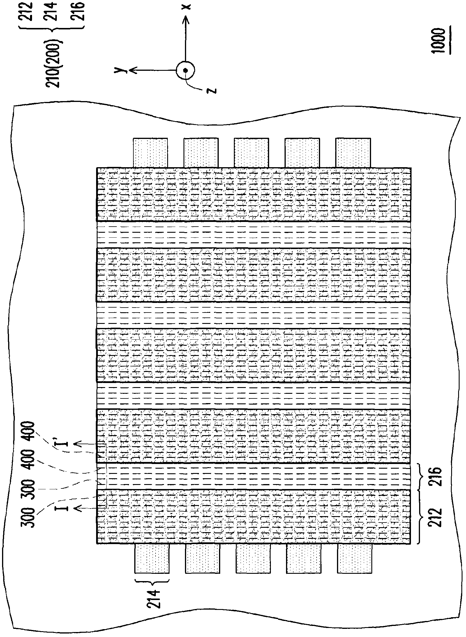
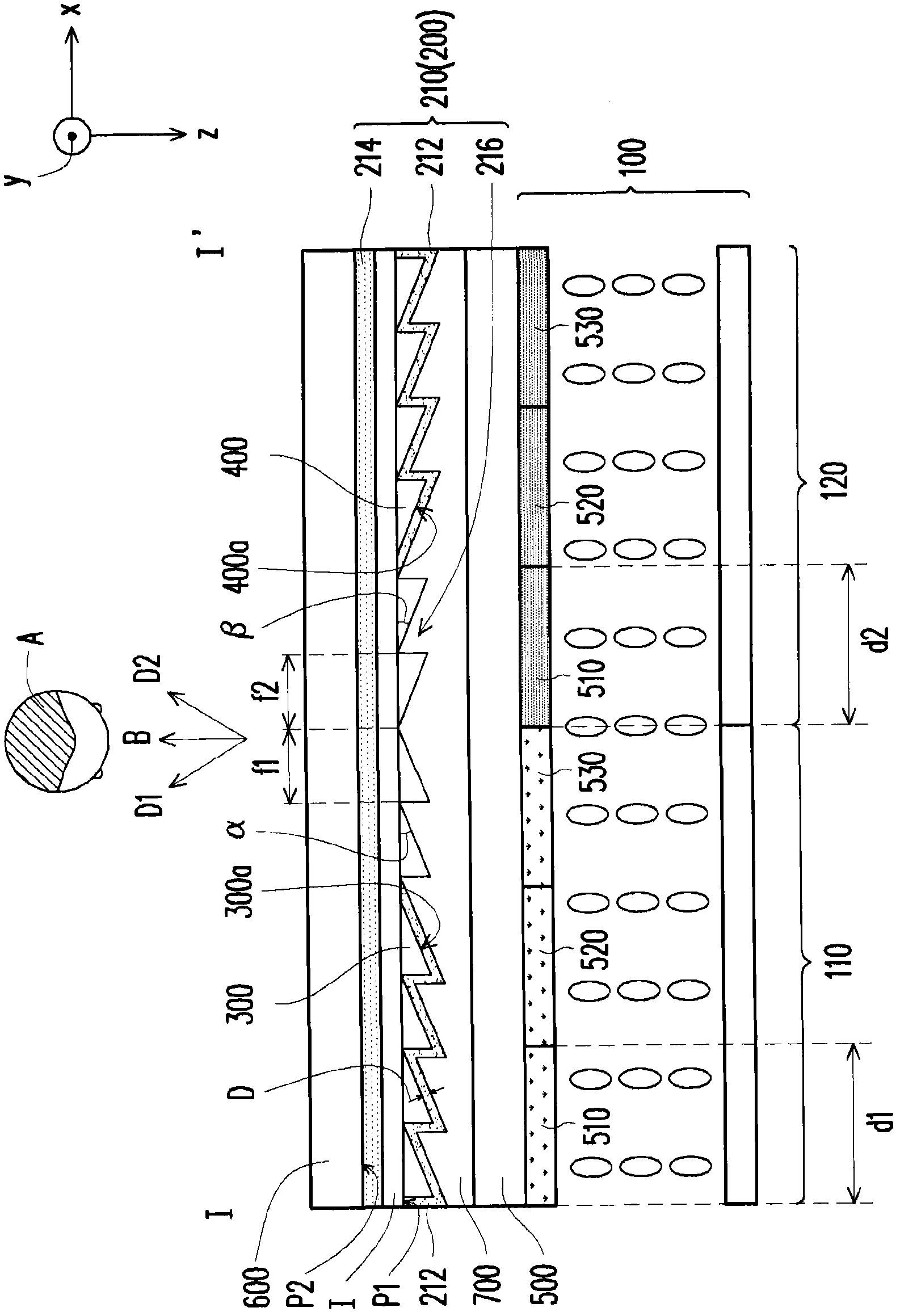
[0051] figure 1 It is a schematic top view of the touch display device according to the first embodiment of the present invention. figure 2 for along figure 1 The cross-sectional schematic diagram drawn by the section line I-I'. Please also refer to figure 1 and figure 2 The touch display device 1000 of this embodiment may include a pixel array 100 , a touch cell array 200 , a plurality of first microprisms 300 and a plurality of second microprisms 400 .

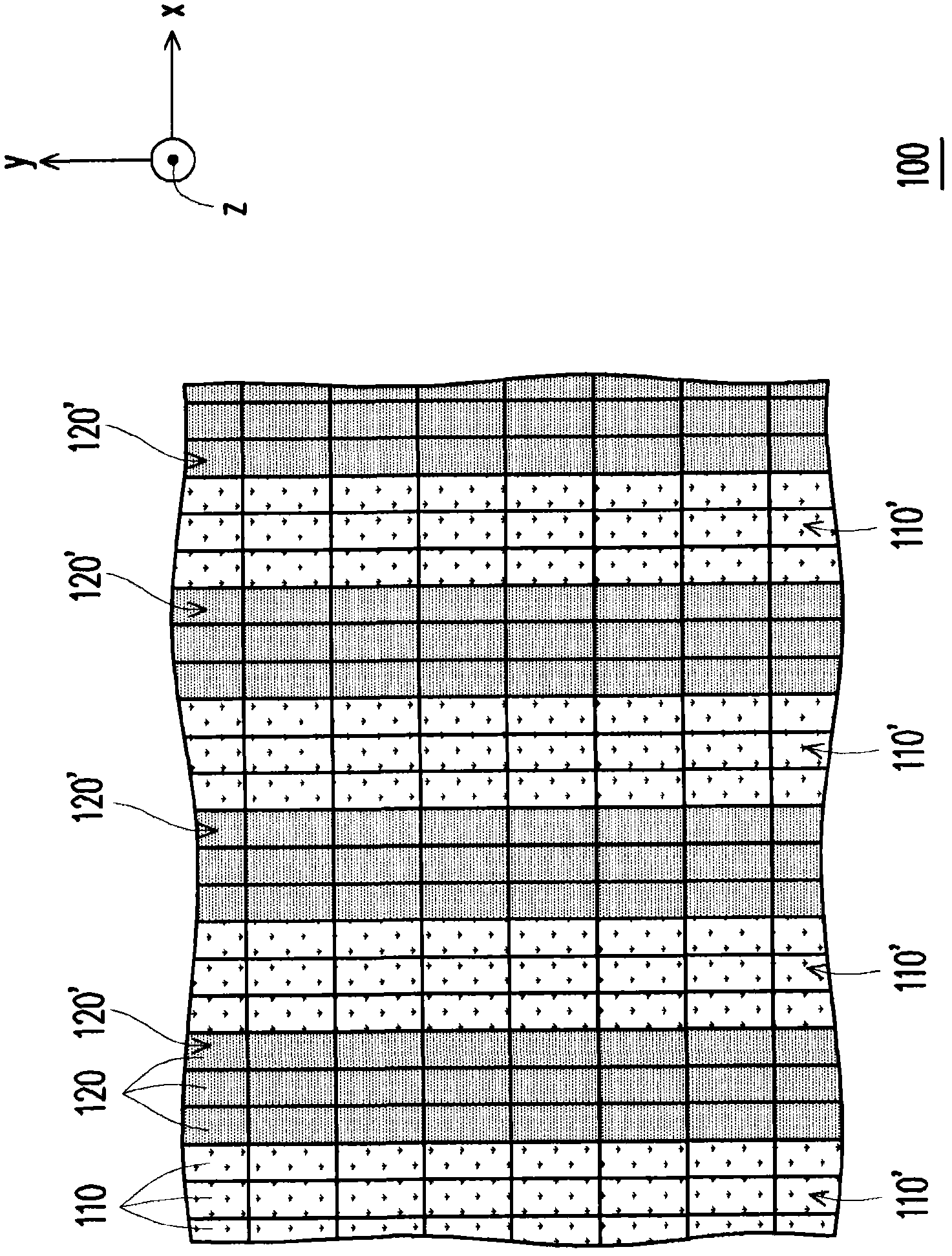
[0052] image 3 It is a schematic top view of the pixel array in the first embodiment of the present invention. Please refer to image 3 , in this embodiment, the pixel array 100 may include a plurality of first pixels 110 and a plurality of second pixels 120 . Specifically, the plurality of first pixels 110 may be multiple groups of first pixel rows 110' arranged along the y direction, and the plurality of second pixels 120 may be multiple groups of second pixel rows 120' arranged along the y direction , wherein t...

no. 2 example

[0062] Figure 6 It is a schematic cross-sectional view of a touch display device according to a second embodiment of the present invention. Please refer to Figure 6 , the touch display device 1000A of this embodiment is similar to the touch display device 1000 of the first embodiment. The following will only explain the differences between the two, and the similarities will not be repeated.

[0063] The touch display device 1000A of this embodiment also includes a touch panel substrate 600 . The difference from the first embodiment is that in this embodiment, the sensing electrodes 210 and the plurality of color filter units 510 , 520 , 530 of the pixel array 100 are jointly disposed on the touch panel substrate 600 . Furthermore, the sensing electrodes 210 and the color filter units 510 , 520 , 530 can be located on the same side of the touch panel substrate 600 , and the color filter units 510 , 520 , 530 cover the sensing electrodes 210 . In this way, the appearance o...

no. 3 example

[0065] The touch display device 1000B of this embodiment is similar to the touch display device 1000 of the first embodiment. The following will only explain the differences between the two, and the similarities will not be repeated.

[0066] Figure 8 It is a schematic top view of the touch display device according to the third embodiment of the present invention. Please refer to Figure 8 , in the touch display device 1000B of this embodiment, the sensing electrodes 210 may include a plurality of bulk electrodes 218 . The bulk electrodes 218 are arranged in an array on a plane K. Referring to FIG. In this embodiment, these block electrodes 218 include a first block electrode 218a and a second block electrode 218b, wherein a plurality of first block electrodes 218a (or second block electrodes 218b) are electrically connected to each other to Multiple first sensing series S1 (or multiple second sensing series S2) are formed, wherein the extension directions of each first s...


PUM


Abstract

The invention provides a touch control display device, comprising a pixel array, a touch control array, a plurality of first micro prisms, and a plurality of second micro prisms. The pixel array comprises a plurality of first pixels and a plurality of second pixels. The touch control unit array comprises a plurality of sensing electrodes. The plurality of first micro prisms and the plurality of second micro prisms are manufactured via integration with at least a part of the sensing electrodes. The first micro prisms are corresponding to the first pixels to output a picture frame image of the first pixels along a first light-outcoming direction, the second micro prisms are corresponding to the second pixels to output the picture frame image of the second pixels along a second light-outcoming direction, wherein the first light-outcoming direction is different from the second light-outcoming direction.

Description

【Technical field】 [0001] The present invention relates to a touch display device, and in particular to a touch display device capable of displaying stereoscopic images. 【Background technique】 [0002] Stereoscopic displays can be classified into two types: stereoscopic and auto-stereoscopic according to usage. The mainstream auto-stereoscopic display technologies include barrier type and lenticular light-splitting technology. Both of the above two technologies use a group of optical microstructures in front of the pixels of the display to project the content displayed by the pixels to the left and right eyes of the user respectively. In addition, touch panel technologies include capacitive, resistive, optical, electromagnetic induction, etc. Among them, the capacitive type has the advantages of high sensitivity and multi-touch, which has become the mainstream touch panel technology. [0003] In order to meet the various needs of users, some industry players have applied the...

Claims


Application Information

Patent Timeline
Patent Type & Authority Applications(China)
IPC IPC(8): G02F1/133G02F1/1335G02F1/1343G02B27/22G06F3/041
Inventor 梅光华郭文瑞林建宏庄堇桦蓝国华邱振伦
Owner AU OPTRONICS CORP
Why Eureka
Try Eureka