
Compression welding device of polar group of battery

A compression device and welding device technology, applied in auxiliary devices, welding equipment, auxiliary welding equipment, etc., can solve the problems of demanding operators' quality and education level, waste of manpower, and large maintenance work of machine loss, so as to reduce product defects rate, the effect of improving production efficiency

Inactive Publication Date: 2011-07-20
ANHUI LEOCH BATTERY TECH
View PDF8 Cites 9 Cited by
  • Summary
  • Abstract
  • Description
  • Claims
  • Application Information

AI Technical Summary

Problems solved by technology

[0002] In the production of valve-regulated sealed lead-acid batteries, especially in the welding production of medium and large dense lead-acid batteries, many factories still use the traditional manual compression of the electrode group into the comb plate, so that the manual compression of the electrode group into the comb Shaped boards are a waste of time and manpower in operation, and the production efficiency is low. Generally, one welding station requires two workers to operate, and this method is likely to cause AGM (Absorptive Glass Mat, ultrafine glass fiber) partitions Crack or pole group dislocation deformation, thus affecting battery quality
Although a kind of COS (Cast On Strap, casting connecting strip) electrode group casting welding is emerging in the lead-acid battery industry, the one-time investment of this kind of machinery and equipment is too high, and the maintenance work of the machine is large, and the quality and education level of the operators are required. Harsh, more difficult to popularize

Method used


Image

  • Compression welding device of polar group of battery
  • Compression welding device of polar group of battery

Examples


Embodiment Construction

[0016] In order to make the object, technical solution and advantages of the present invention clearer, the present invention will be further described in detail below in conjunction with the accompanying drawings and embodiments.

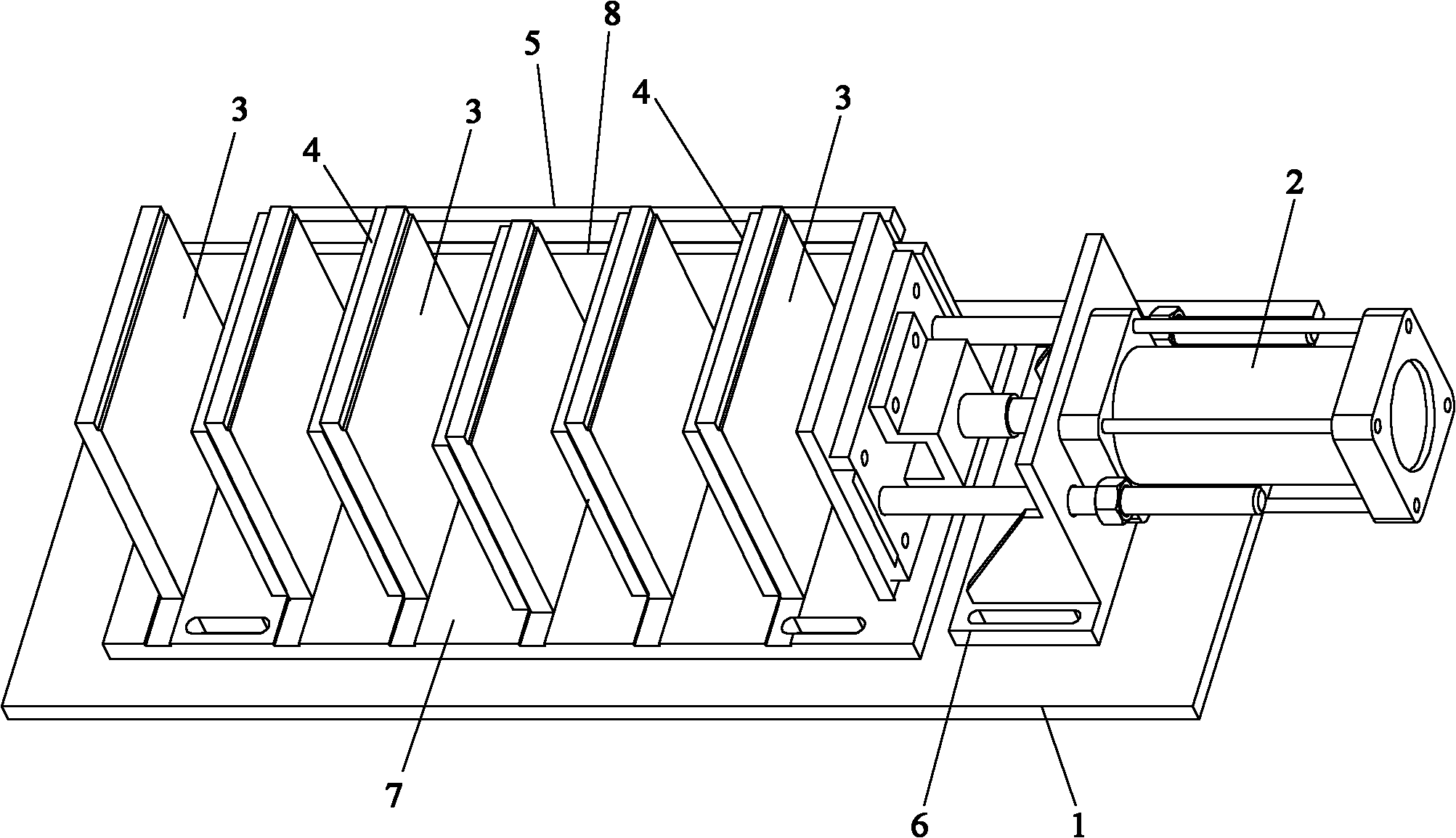
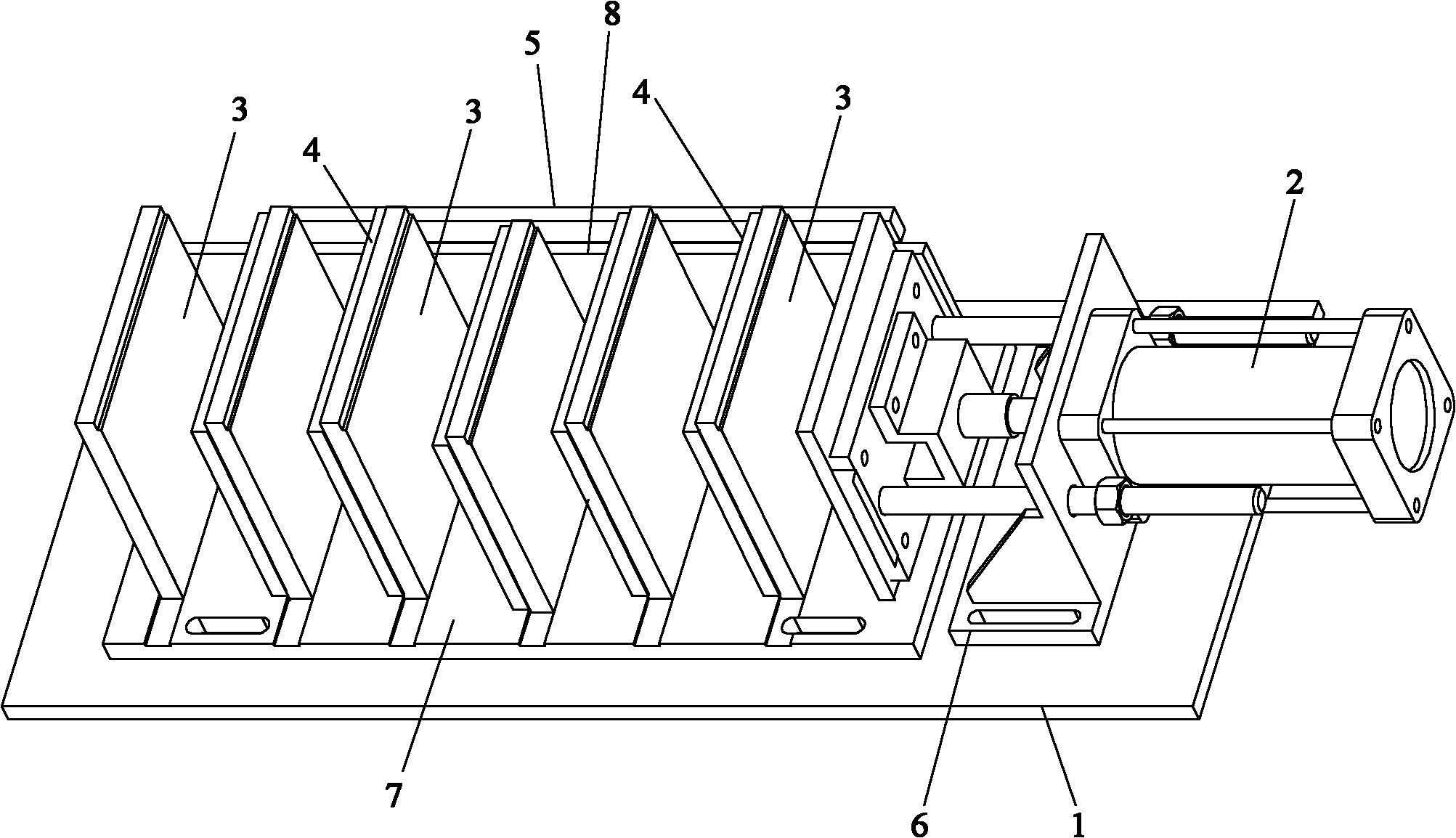
[0017] see figure 1 as shown, figure 1 It is a structural schematic diagram of a storage battery electrode group compression welding device provided by the present invention. As shown in the figure, the compression welding device includes a first bottom plate 1, a compression device 2, a plurality of fixed plates 3, a plurality of movable plates 4, and a movable plate connecting plate 5 for fixing the movable plates 4, wherein the compression device 2 The fixed plate 3 is fixed on the bottom plate 1, the movable plate connecting plate 5 is connected with the compression device 2, and the compressing device 2 drives the movable plate connecting plate 5 and the movable plate 4 to move together.

[0018] In order to make the compression distance of ...


PUM


Abstract

The invention discloses a compression welding device of a polar group of a battery, and the compression welding device comprises a first baseplate (1), a compression device (2), a plurality of fixed plates (3), a plurality of movable plates (4) and moving plate connecting plates (5) for fixing the movable plates (4), wherein the compression device (2) and the fixed plates (3) are fixed on the baseplate (1), the movable plate connecting plates (5) are connected with the compression device (2), and the compression device (2) is used for driving the movable plate connecting plates (5) and the movable plates (4) to move together. By arranging the compression device (2), the plurality of the fixed plates (3) and the plurality of the movable plates (4) on the first baseplate (1), the compression device can be used for driving the movable plates to move so as to perform compression welding on the polar group, thereby being applicable to welding the polar groups in different sizes, greatly improving the production efficiency and reducing the rejection rate of products.

Description

technical field [0001] The invention relates to the technical field of batteries, in particular to a battery electrode group compression welding device. Background technique [0002] In the production of valve-regulated sealed lead-acid batteries, especially in the welding production of medium and large dense lead-acid batteries, many factories still use the traditional manual compression of the electrode group into the comb plate, so that the manual compression of the electrode group into the comb Shaped boards are a waste of time and manpower in operation, and the production efficiency is low. Generally, one welding station requires two workers to operate, and this method is likely to cause AGM (Absorptive Glass Mat, ultrafine glass fiber) partitions Cracks or dislocation deformation of the pole group will affect the quality of the battery. Although a kind of COS (Cast On Strap, casting connecting strip) electrode group casting welding is emerging in the lead-acid battery...

Claims


Application Information

Patent Timeline
IPC IPC(8): B23K37/00H01M2/26
CPCY02E60/12Y02E60/10
Inventor 彭小勐何广富陈伟
Owner ANHUI LEOCH BATTERY TECH
Learn More