Wear-resisting device of receiving liner plate of band conveyor

A belt conveyor and anti-wear technology, which is applied in the direction of transportation and packaging, conveyors, conveyor objects, etc., can solve the problem of too fast wear of the liner, achieve the effects of avoiding severe friction, reducing wear, and improving service life

Inactive Publication Date: 2011-07-20
TAIYUAN HEAVY IND
View PDF8 Cites 0 Cited by
  • Summary
  • Abstract
  • Description
  • Claims
  • Application Information

AI Technical Summary

Problems solved by technology

The method of improving the performance of the liner alone can

Method used


Image

  • Wear-resisting device of receiving liner plate of band conveyor
  • Wear-resisting device of receiving liner plate of band conveyor

Examples


Example Embodiment

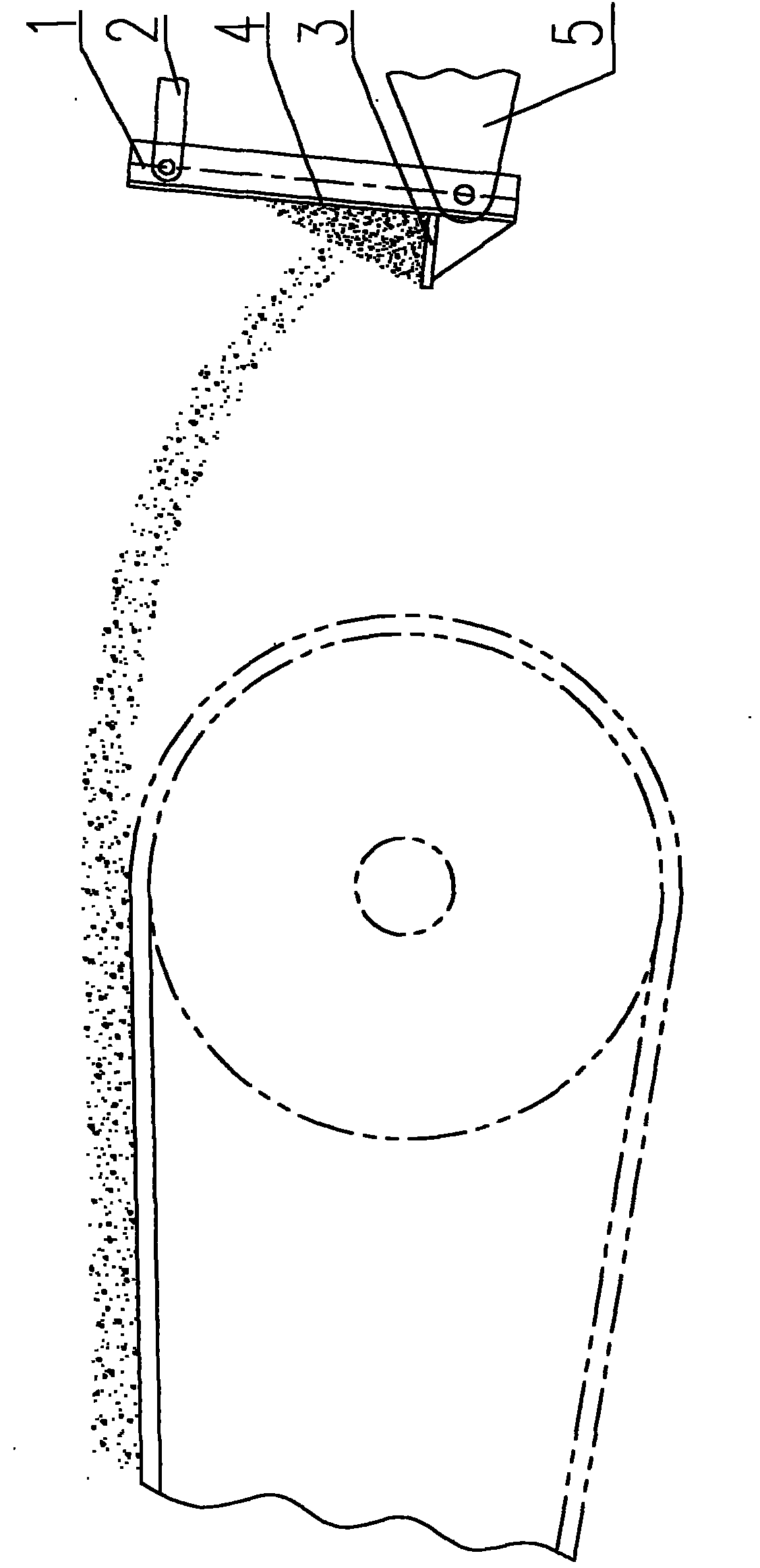
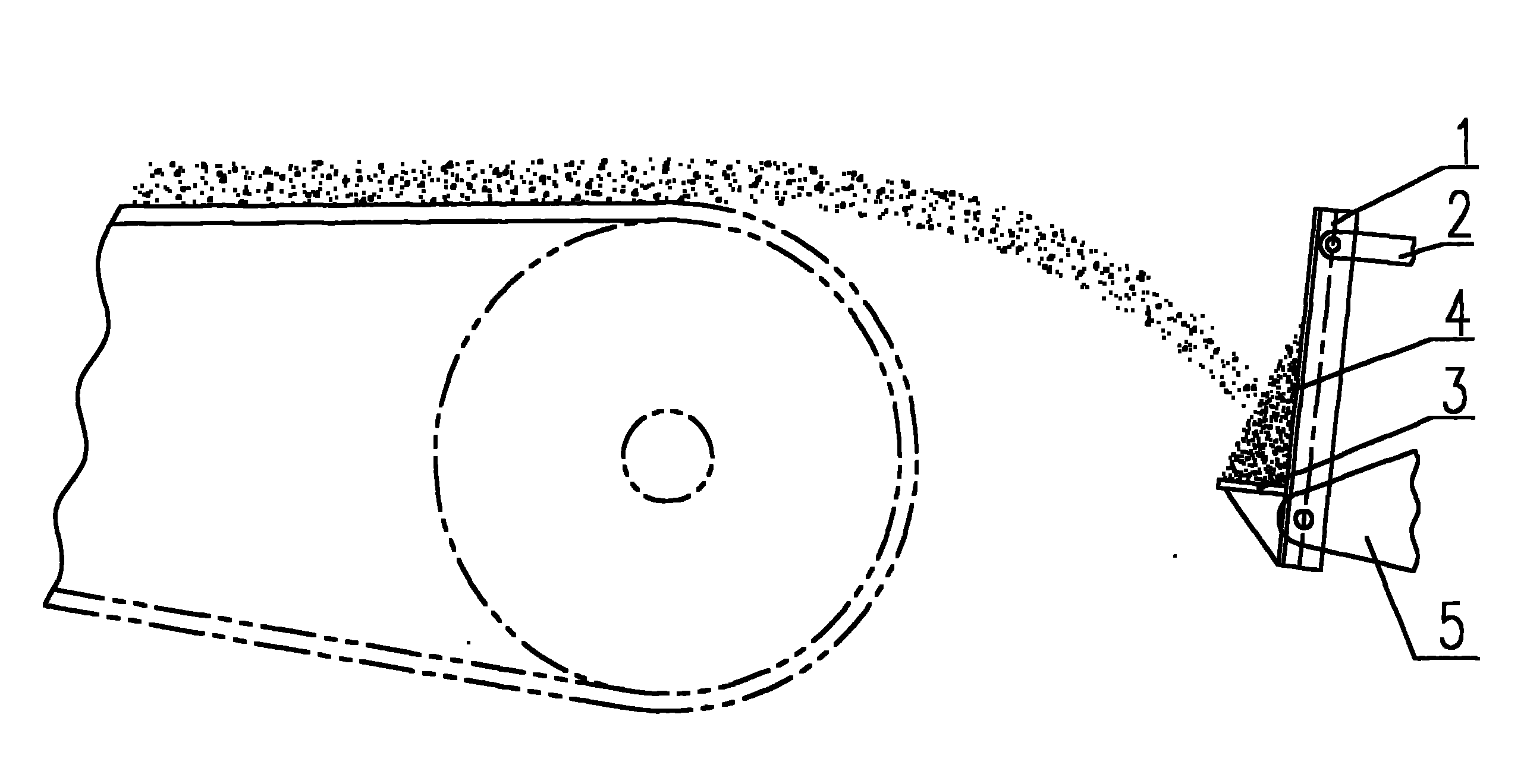
[0011] Such as figure 1 As shown, an anti-wear device for the material receiving liner of a belt conveyor is composed of a bracket 1 installed on the conveyor frame 5, a liner 4 fixed on the bracket 1, an adjusting rod 2 and a baffle 3.

[0012] The bracket 1 is welded (material-receiving plate) 3 at a certain angle, the upper part of the bracket 1 is connected with the adjusting rod 2, and the lower part of the bracket 1 is hinged with the conveyor frame 5.

[0013] Due to the different running speed of the material, the position on the liner is also different. In order to make the material directly fall on the accumulated material of the baffle, the support 1 is designed to be adjustable. The angle of the bracket 1 can be adjusted through an adjusting rod 2 hinged to it.

[0014] According to actual working conditions, the present invention can be installed on the discharge end or the receiving end of the belt conveyor.

[0015] The working process of the present invention:

[0016]...


PUM


Abstract

The invention relates to a wear-resisting device of a receiving liner plate of a band conveyor, in particular to a liner plate of a discharging/receiving end of a band conveyor and solving the problem of too rapid wear of the liner plate. The wear-resisting device comprises a bracket arranged on a conveyor stand and a liner plate fixed on the bracket. The wear-resisting device is characterized in that a baffle plate is welded by forming a certain angle with the bracket. The upper part of the bracket is connected with a regulating rod and the lower part is hinged with the conveyor stand. The wear-resisting device can be arranged at the discharging end or receiving end of the band conveyor. When materials fall on the liner plate, part of materials are remained on the baffle plate to ensure that a material layer with certain thickness is formed in front of the liner plate, thus the collision of particular materials to the liner plate is buffered, the wear of the liner plate is reduced, the service life of the liner plate is prolonged, the period of replacing the liner plate is expanded and the factory shutdown losses are reduced.

Description

technical field [0001] The invention relates to a liner plate at the discharging / receiving end of a belt conveyor. Background technique [0002] In order to prevent wear, the belt conveyor is equipped with a liner on the structural surface of the discharge / receiving end that contacts the material. Due to the impact of the material, the liner wears very quickly, and the liner needs to be replaced frequently. Due to the narrow location, it is inconvenient to replace the liner, and the loss of downtime for replacement is relatively large. Most of the existing technologies improve the wear resistance by improving the physical properties of the liner material. Due to the fast running speed of the belt and the gravity of the material, the impact on the liner is aggravated. Only by improving the performance of the liner, the problem of too fast wear of the liner cannot be effectively solved. Contents of the invention [0003] The purpose of the present invention is to overcome...

Claims


Application Information

Patent Timeline
IPC IPC(8): B65G41/00B65G15/00
Inventor 仝雷强
Owner TAIYUAN HEAVY IND
Why Eureka
Try Eureka