
A sintering machine bellows end sealing device and its control method

A technology of end sealing and sintering machine, which is applied in the direction of furnace safety device, furnace, charge control, etc., can solve the problems of sintering machine damage, wear, and reduced flexibility of the rotating structure of the sealing device, so as to prolong the service life of the equipment and improve the work efficiency. Safety factor, effect of improving sintering effect

Active Publication Date: 2020-05-22
CHANGSHA UNIVERSITY OF SCIENCE AND TECHNOLOGY
View PDF7 Cites 0 Cited by
  • Summary
  • Abstract
  • Description
  • Claims
  • Application Information

AI Technical Summary

Problems solved by technology

[0007] There is relative sliding between the sealing plate of the sealing device and the bottom beam of the trolley, and there are a lot of trolleys. Under long-term action, the friction of the bottom beam of the trolley will cause the sealing plate to wear and leak air, especially when the bottom of the trolley collapses, the sealing The position corresponding to the collapsed waist on the board is more prone to local wear and tear, which is in the shape of a gully, resulting in air leakage
[0008] Since the sealing device works in a high-temperature and dusty working environment, the flexibility of the rotating structure of the sealing device decreases after working for a period of time, resulting in the sealing plate not being able to rebound to the normal working position after being squeezed and moved down by the collapsed trolley, resulting in a large amount of air leakage
[0009] Most of the traditional sealing devices are mechanical self-adjusting seals. When the sealing plate cannot rebound and reset or the partial wear of the sealing plate causes air leakage, or there are abnormalities in the collapse of the waist of multiple consecutive trolleys, it cannot be discovered and dealt with in time.
[0010] 2. When the trolley collapses too severely, it may collide with the sealing device and get stuck. If it is not found in time, it will easily cause damage to the sintering machine. The traditional sealing device cannot detect and deal with the jamming of the trolley in time
[0011] 3. Particles such as dust are often bonded to the bottom beam of the trolley, which will lead to increased wear and tear when the bottom beam of the trolley and the sealing plate are in contact with each other.

Method used


Image

  • A sintering machine bellows end sealing device and its control method
  • A sintering machine bellows end sealing device and its control method
  • A sintering machine bellows end sealing device and its control method

Examples


Embodiment Construction

[0037] The present invention will be described in detail below in conjunction with specific embodiments shown in the accompanying drawings. However, these embodiments do not limit the present invention, and any structural, method, or functional changes made by those skilled in the art according to these embodiments are included in the protection scope of the present invention.

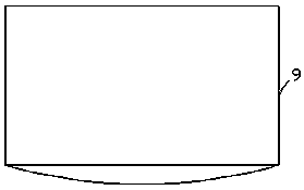
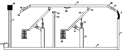
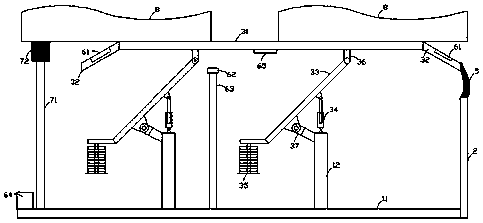
[0038] It should be noted, Figures 2 to 5 The sealing device at the end of the bellows of the sintering machine shown is all set at the head end of the bellows 2, if it is set at the tail end of the bellows 2, it will be at the end of the bellows Figures 2 to 5 The sealing device at the end of the bellows of the sintering machine shown is basically a mirror image.

[0039] See figure 2 , a sintering machine bellows end sealing device, comprising a base mechanism, a counterweight four-bar linkage self-adjusting mechanism, and a detection and alarm mechanism;

[0040]The base mechanism includes a b...


PUM


Abstract

The invention provides a sintering machine air box end portion sealing device. The sintering machine air box end portion sealing device comprises a base mechanism, a counterweight four-connection-rodself-adjusting mechanism and a detection alarm mechanism, wherein the counterweight four-connection-rod self-adjusting mechanism comprises a sealing plate, transition plates, rotating parts, hydrauliccylinders and counterweight blocks, the detection alarm mechanism comprises air leakage sensors, a contact sensor, a second support and an alarm processor, and the alarm processor judges whether to issue a corresponding alarm or not and whether to control the hydraulic cylinders to act or not by analyzing feedback values of the air leakage sensors and the contact sensor. The invention further provides a control method for the sintering machine air box end portion sealing device. According to the sintering machine air box end portion sealing device and the control method thereof, the sensors collect working condition parameters of the sealing device and perform feedback to the alarm processor to perform analyzing, exceptional situations that the sealing plate cannot be restored or partialwear of the sealing plate leads to air leakage or continuous multiple trolleys are all collapsed and the like can be detected and disposed in time, the air leakage rate in the sintering production process can be greatly reduced, the sintering rate is increased and the sintering effect is improved.

Description

technical field [0001] The invention relates to the technical field of sintering machine sealing, in particular to a sealing device for the end of a sintering machine bellows. The invention also relates to a control method for the sealing device at the end of the bellows of the sintering machine. Background technique [0002] The sintering machine is one of the main equipments for large-scale iron ore agglomeration in the metallurgical industry. It mainly transports ore powder on the track through the trolley, and provides negative wind pressure through the bellows under the trolley to make the top-ignited ore placed on the trolley seep downward, and gradually ignite the ore layer downwards. To achieve the purpose of complete sintering. Therefore, the quality of the sintering effect has a lot to do with the negative wind pressure provided by the bellows. [0003] In the actual production process, the negative wind pressure provided by the bellows cannot fully act on the m...

Claims


Application Information

Patent Timeline
Patent Type & Authority Patents(China)
IPC IPC(8): F27D99/00F27D3/12F27D7/02F27D21/00F27D21/04
CPCF27D3/123F27D7/02F27D21/00F27D21/04F27D99/0076F27D2021/0092
Inventor 吴钢王鑫刘志强张健李岳林
Owner CHANGSHA UNIVERSITY OF SCIENCE AND TECHNOLOGY
Learn More