Suspension apparatus of ship main engine
A suspension device and ship main engine technology, which is applied in the direction of transportation and packaging, load suspension components, etc., can solve the problems of large overall force on the suspension beam, complex structure, and troublesome production, so as to achieve a firm structure of the suspension beam and ensure safety , the effect of low production cost
- Summary
- Abstract
- Description
- Claims
- Application Information
AI Technical Summary
Problems solved by technology
Method used
Image
Examples
Embodiment 1
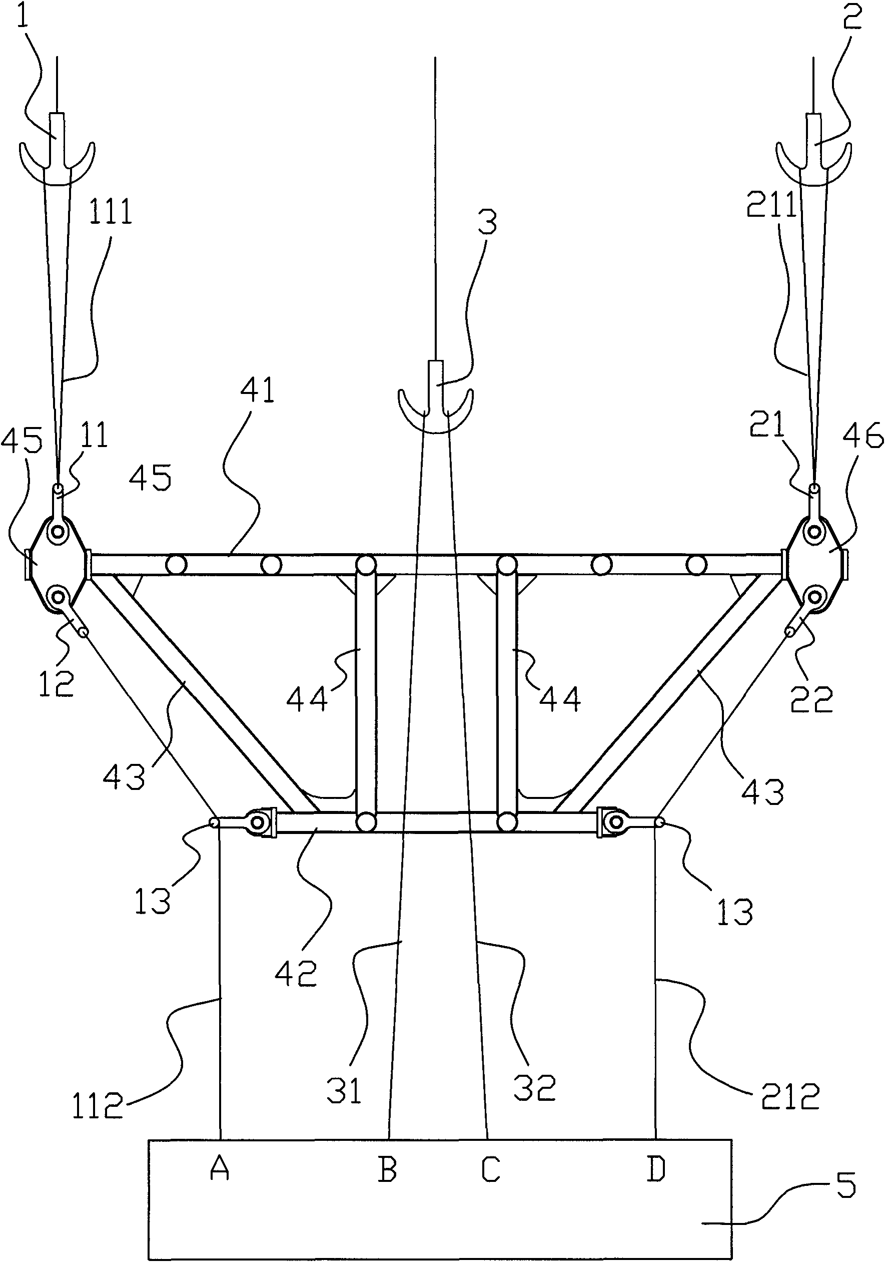
[0019] The first embodiment, the suspension device of the main ship of the present embodiment includes a steel wire rope and a hanger. The wire rope includes a first wire rope 111, a second wire rope 211, a third wire rope 112, a fourth wire rope 212 and a middle wire rope. The top left end of the hanger is connected to the first traction part through the first wire rope 111. The top right end is connected to the second traction part by a second wire rope 211, the bottom left end of the hanger is extended to the first hanging point A of the host 5 through the third wire rope 112, and the bottom right end of the hanger is passed through the fourth wire rope 212 Extending to the fourth lifting point D of the host 5, the middle of the hanger is provided with a space for the middle wire rope to extend from top to bottom through the middle of the hanger to the corresponding second lifting point B and third lifting point C, so The upper end of the middle wire rope is connected with t...
Embodiment 2
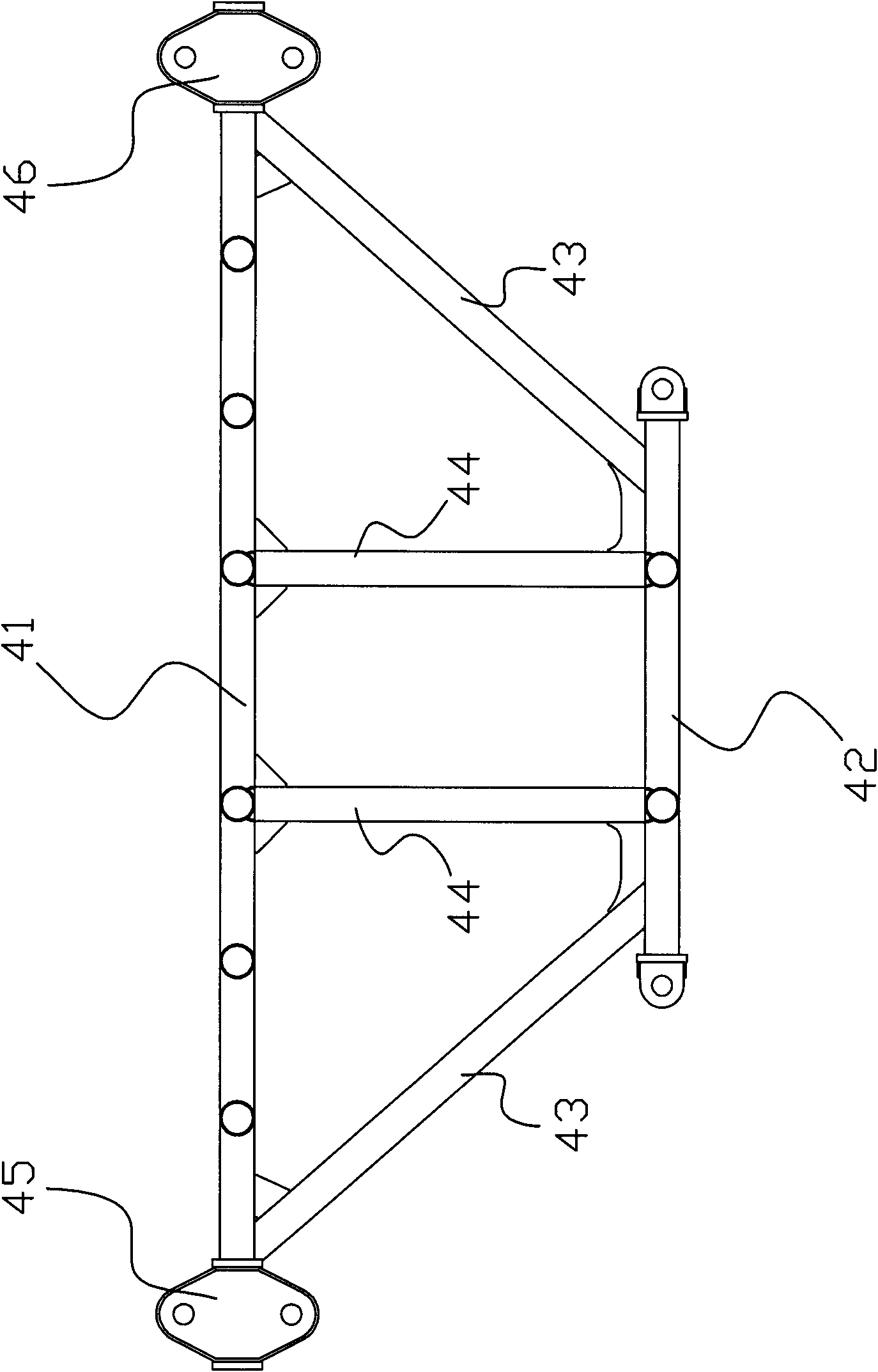
[0021] Example two, such as Figure 1 to 4 As shown, the hanger of this embodiment includes an upper beam 41 and a lower beam 42, the upper beam 41 and the lower beam 42 are connected by connecting rods, the upper beam 41 is wide and the lower beam 42 is narrow. Trapezoid, the lower end of the first steel wire rope 111 is connected to the left end of the upper beam 41, the lower end of the second steel wire rope 211 is connected to the right end of the upper beam 41, and the upper end of the third steel wire rope 112 passes through the left end of the lower beam 42 The movable lifting lug 13 is connected to the left end of the upper beam 41, and the upper end of the fourth wire rope 212 passes through the movable lifting lug 13 at the right end of the lower beam 42 and is connected to the right end of the upper beam 41. The left end of the upper beam 41 is provided with a left hanging plate 45, the upper part of the left hanging plate 45 is detachably provided with a movable fi...
PUM
 Abstract
Description
Claims
Application Information
 - R&D
- Intellectual Property
- Life Sciences
- Materials
- Tech Scout
- Unparalleled Data Quality
- Higher Quality Content
- 60% Fewer Hallucinations
Browse by: Latest US Patents, China's latest patents, Technical Efficacy Thesaurus, Application Domain, Technology Topic, Popular Technical Reports.
© 2025 PatSnap. All rights reserved.Legal|Privacy policy|Modern Slavery Act Transparency Statement|Sitemap|About US| Contact US: help@patsnap.com


