
Improved bidirectionally stressed foundation knot attached to lifting scaffold

A technology for attaching lifting and scaffolding, applied in the accessories of scaffolding, scaffolding supported by housing structure, housing structure support, etc., can solve the problems of high risk, affect safety, low construction efficiency, etc., and achieve excellent bending moment resistance and anti-bending Torque, improve overall safety performance, and improve the effect of construction efficiency

Active Publication Date: 2011-07-20
苏茂兵
View PDF11 Cites 4 Cited by
  • Summary
  • Abstract
  • Description
  • Claims
  • Application Information

AI Technical Summary

Problems solved by technology

In this way, whether it is cable-stayed or vertically pulled, or whether it is centrally suspended or eccentrically suspended, the force on the single-piece vertical main frame is unbalanced, which is very dangerous. The root cause of the frequent fall accidents of the attached lifting scaffolding of the main frame structure
In addition, this kind of frame structure assembled with rod-shaped structural parts and fastening fasteners is difficult to achieve standardized construction, the construction efficiency is low, and the construction quality is difficult to guarantee. As a result, there are often many problems in the attached lifting scaffold that are difficult to find or predict in advance. Weak points, especially the connection between the vertical main frame and the horizontal support truss, often become an important factor affecting safety
Although there is currently a standardized way of construction in the vertical frame of conventional hoisting machinery (there are usually only vertical frames in conventional hoisting equipment), it is still difficult to implement in the attached lifting scaffold.

Method used


Image

  • Improved bidirectionally stressed foundation knot attached to lifting scaffold
  • Improved bidirectionally stressed foundation knot attached to lifting scaffold
  • Improved bidirectionally stressed foundation knot attached to lifting scaffold

Examples


Embodiment Construction

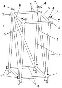
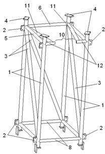
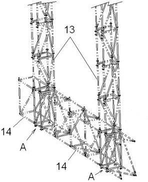
[0020] figure 1 What is shown is a structural form of the two-way force-bearing foundation section of the improved attached lifting scaffold of the present invention. Two sets of parallel horizontal rods (such as iron pipes, steel pipes, etc., the same below) 6, 8, two sets of parallel front and rear longitudinal rods 5 on the left and right, and two sets of parallel vertical rods 1 are fixed The connecting plates with holes on the rod-shaped members are fastened by bolts to form a stable integral rectangular hexahedron frame structure, in which at least one pair of non-adjacent end points in at least one plane formed by adjacent rod-shaped members are connected Diagonal strut 3 is arranged. As shown in the figure, a diagonal strut 3 is respectively arranged in three different planes of the frame structure. At the upper and lower ends of each vertical rod-like member 1, there are respectively disc-type connection plate structures 4 with connection holes 7, wherein the connec...


PUM


Abstract

The invention discloses an improved bidirectionally stressed foundation knot attached to a lifting scaffold. In a right-angle hexahedron framework structure formed by mutually and stably connecting upper and lower two groups of parallel transverse rodlike members, left and right two groups of parallel fore-and-aft rodlike members and front and back two groups of parallel vertical rodlike members, an inclined brace rod is connected between at least a pair of non-adjacent end points in at least one plane formed by the adjacent rodlike members, upward and downward direction ends of each vertical rodlike member are respectively provided with a vertical connection structure, and two direction ends of each transverse rodlike member are respectively provided with a transverse connection structure. The foundation knot is more reasonable and scientific on the stress distribution of a lifting acting force, has better bidirectional stress performances for resisting bending moment and torsion moment, and can ensure that a vertical main framework and a horizontal supporting truss attached to the lifting scaffold realize standardized construction by means of installation of the standard knot.

Description

technical field [0001] The invention relates to a hoisting machine with vertical transportation function, in particular to an attached lifting scaffold for building construction. Background technique [0002] Attached lifting scaffolding in building construction is a special lifting machine with vertical lifting movement / transportation functions. Its particularity is mainly reflected in the fact that it is built around the perimeter of the building during building construction and needs to be lifted with the progress of building construction. , and also has a certain height of suspended movement overall structure scaffolding, that is, its structure must have a vertically extending main frame and a horizontally extending load-bearing support truss. When it is driven by the lifting equipment scattered throughout the building to carry out the lifting / lowering movement, it is required to ensure the synchronous consistency of the overall structure, otherwise the uneven local forc...

Claims


Application Information

Patent Timeline
IPC IPC(8): E04G5/00E04G3/28
Inventor 苏茂兵
Owner 苏茂兵
Learn More