
Fluid control device for endoscope

A technology of fluid control device and endoscope, which is applied in the direction of endoscope, application, medical science, etc., and can solve problems such as backflow of aspirated matter and difficulty in adjusting the bias force of blocking membrane 7

Active Publication Date: 2011-07-20
OLYMPUS CORP
View PDF7 Cites 4 Cited by
  • Summary
  • Abstract
  • Description
  • Claims
  • Application Information

AI Technical Summary

Problems solved by technology

In addition, it may be difficult to adjust the biasing force on the blocking film 7
[0018] In addition, although it is also possible to suck the plunger body 2 to make the inside of the cylinder 1 a negative pressure, when the negative pressure in the air supply pipeline 6 reaches an excessively high negative pressure, it will also cause the aspirated material to flow to the air supply hose side. countercurrent

Method used


Image

  • Fluid control device for endoscope
  • Fluid control device for endoscope
  • Fluid control device for endoscope

Examples


Embodiment Construction

[0049] Embodiments of the present invention will be described in detail below.

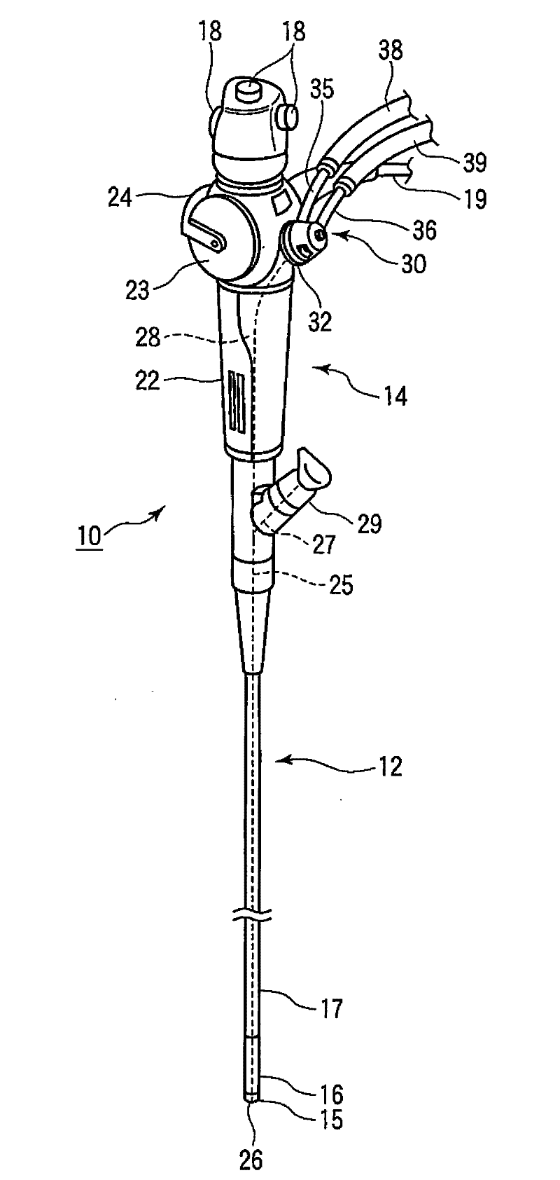
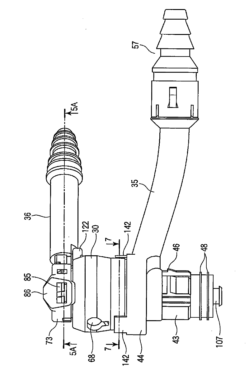
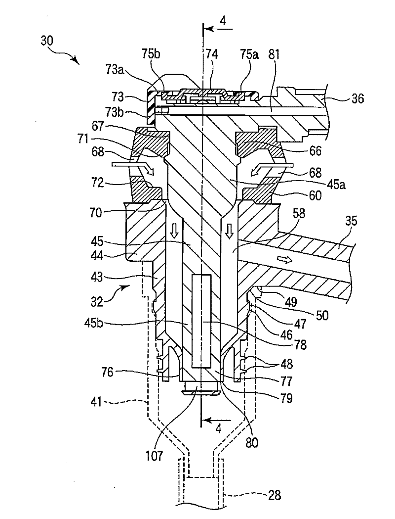
[0050] figure 1 It is a perspective view showing an endoscope 10 of an endoscope apparatus according to an embodiment of the present invention. The endoscope 10 has an elongated endoscope insertion portion 12 inserted into a body cavity, and an endoscope operation portion 14 connected to a proximal end of the endoscope insertion portion 12 . The endoscope insertion portion 12 is constituted by sequentially connecting a distal end forming portion 15 , a bending portion 16 to be bent, and a long and flexible flexible tube portion 17 from the distal end side. An unillustrated illumination window and an observation window for imaging are provided on the tip configuration portion 15 . Thus, when the endoscope insertion unit 12 is inserted into the body cavity, the inside of the body cavity or the like is imaged and observed. The endoscope manipulation unit 14 has an endoscope grip unit 22 to be gri...


PUM


Abstract

A fluid control device (30) for an endoscope is provided to an endoscope (10) having a single conduit (25, 28) for performing suction and gas delivery and controls gas delivery and suction relative to the conduits (25, 28). The fluid control device (30) is provided with: gas delivery conduits (39, 81, 84, 85, 88, 91, 82) communicating with the single conduit (25, 28); a suction conduit (38) communicating with the single conduit (25, 28); a first valve (95) provided in the gas delivery conduit (39, 81, 84, 85, 88, 91, 82) and opening only during gas delivery; and a second valve (105) provided to an operation button (74) for performing suction operation and, when the operation button (74) is operated, interrupts the communication between one (81) of the gas delivery conduits (81, 84, 85, 88, 91, 82), which penetrate through the operation button (74), and the other (82) of the gas delivery conduits.

Description

technical field [0001] The present invention relates to a fluid control device that performs air supply and suction through one pipeline in an endoscope and controls fluid flow. Background technique [0002] Generally, an endoscope has an insertion portion inserted into a body cavity, and an operation portion connected to a proximal end of the insertion portion. The endoscope has a conduit (channel) through which fluid flows in the insertion portion, and the conduit is used for air supply, water supply, or suction. The movement of the fluid is controlled by a fluid control device disposed on the operation portion (see Patent Documents 1 to 3). [0003] In recent years, air supply and suction are performed through a single channel of the endoscope. In this case, a fluid control device has been proposed in which switching control between air supply and suction is performed using a single valve device (Patent Document 4). The valve device is Figure 15 valve assembly shown. ...

Claims


Application Information

Patent Timeline
IPC IPC(8): A61B1/00
CPCA61B1/015A61B1/00068
Inventor 牛岛孝则
Owner OLYMPUS CORP
Learn More