Member for temporarily recovering road surface and method for temporarily recovering road surface

A construction method, a temporary technology, applied to roads, roads, special pavements, etc., which can solve problems such as steps, obstacles to comfortable driving of vehicles, and complex structures of pressing parts

Inactive Publication Date: 2011-07-20
MEIWA IND CO LTD
View PDF3 Cites 8 Cited by
  • Summary
  • Abstract
  • Description
  • Claims
  • Application Information

AI Technical Summary

Problems solved by technology

[0009] In the construction method using the above-mentioned conventional pad member for temporary repair, as disclosed in Patent Documents 1 and 2, it has a dual structure of pressing member / dummy roadbed material and rubber pad. When the vehicle is temporarily repaired When driving on the road, the weight of the vehicle is supported by the pressing part / dummy roadbed material, so there is no special problem. However, since the structure of the pressing part is complicated, and the dummy roadbed material also requires corresponding production costs, it is still necessary There is a cost problem
[0010] In addition, during construction, it is necessary to make the excavation width correspond to the width of the pressing member or the simulated roadbed material, and in backfilling, it is also necessary to carry out backfilling at a low level corresponding to the thickness of the rolled body or the simulated roadbed body, and the height of the backfill is high or Low will produce steps, so there are problems in its construction
[0011] Also, when the vehicle is driven in the temporary repair state, in many cases the backfilled sand will be rolled down by the weight of the vehicle and sink
When a step is formed on the temporarily repaired road surface due to the subsidence, there is also a problem that the comfortable driving of the vehicle is hindered.

Method used


Image

  • Member for temporarily recovering road surface and method for temporarily recovering road surface
  • Member for temporarily recovering road surface and method for temporarily recovering road surface
  • Member for temporarily recovering road surface and method for temporarily recovering road surface

Examples


Embodiment Construction

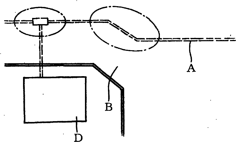
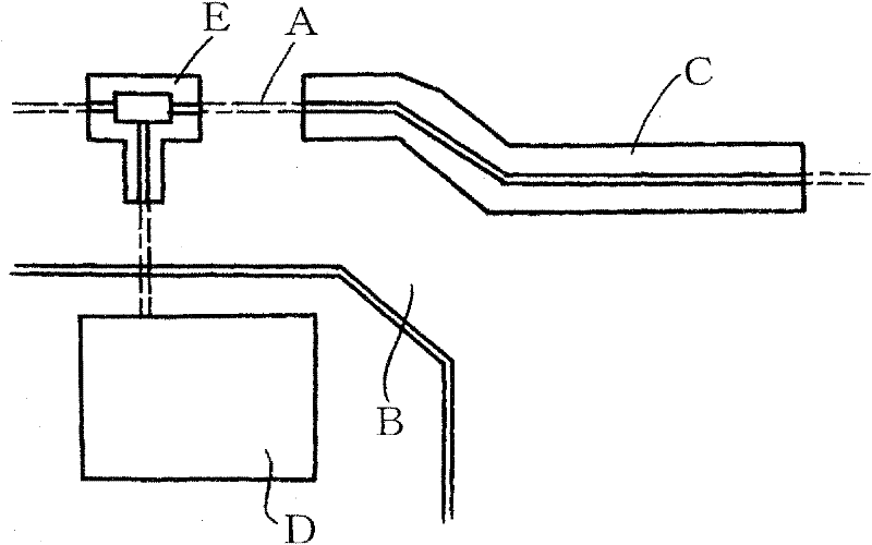
[0047] Next, embodiments of the present invention will be described. As the object of the present invention, mainly as figure 1 Temporary repair work (first embodiment) when excavating a long excavation trench C on the road surface B such as the replacement work of the buried pipeline A shown in the illustration, and excavation is used for replacement / installation of buried equipment (branch pipes) or for Temporary repair work (second embodiment) at the time of excavating a hole E for installing an inlet pipe to a building D is targeted.

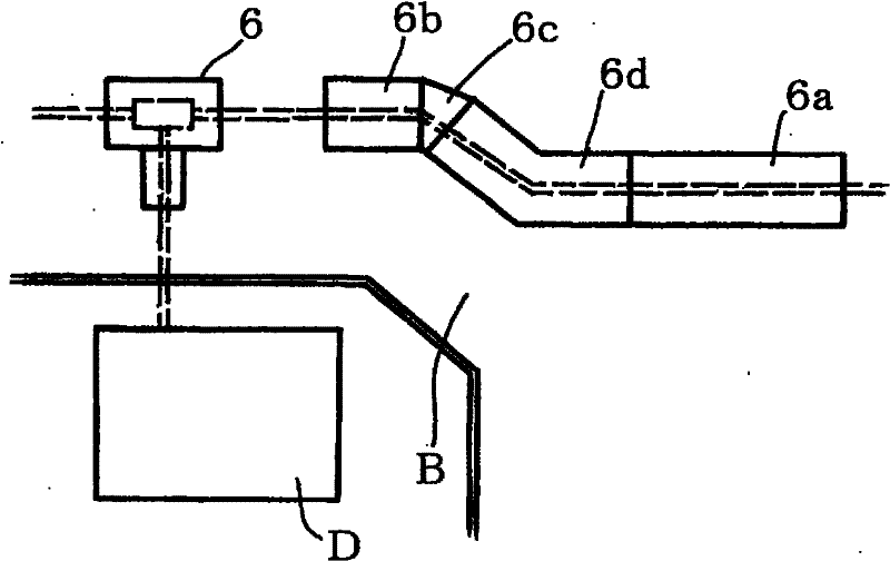
[0048] The road surface temporary repair part used in the first embodiment is composed of the following parts: a liner 1 (1a, 1b, 1c...); an anti-deflection pin 2; an anti-dropping pin 3; a stopper 4, 4a; a fixing pin 5 ; And the scale plate 6 (6a, 6b, 6c...) constitutes.

[0049] The liner 1 is a rectangular rubber sheet with suitable flexibility and firmness used as a conventional pavement liner, and is basically longer than the width of...


PUM


Abstract

Provided is members for temporarily recovering (a lining mat (1), a nonslip pin (2), a lock pin (3), a stopper (4), a fixing pin (5)) that simplify the temporary recovering work of a road surface when pipeline construction work is performed by excavating a pavement surface (B), and also provided is a method for recovering a road surface by using the above-mentioned members. The lining mat (1) is a rectangular rubber board having a thick central portion (11) and thin side portions (12) at the opposite bases, and is provided, at appropriate positions, with pinholes (16) penetrating the front and back surfaces. The lining mat (1) is laid to cover a backfilled surface such that the side end of the lining mat is located on the pavement surface (B), and fixed by driving a tubular nonslip pin (2) into the pinhole and driving the lock pin (3) into the tubular portion of the nonslip pin, and then adjoining mats are connected by inserting the latching protrusion (42) of the stopper (4) into the pinhole.

Description

technical field [0001] The present invention relates to a liner member used for temporarily repairing a road surface when excavating a road surface for gas, water pipe, sewer and other pipeline works, and a road surface temporary repair construction method using the same. Background technique [0002] Trench excavation is carried out during the piping work for laying new pipes on the road surface, or the temporary piping work or regular piping work for the maintenance and replacement of existing gas, natural water pipes, sewer pipes, etc. Backfill the trenches excavated at each stage (usually one day's work), and implement temporary asphalt pavement (temporary repair work) on the upper surface of the backfill so as not to hinder the driving and walking of vehicles. [0003] When this piping work is completed, the asphalt pavement of the above-mentioned temporary repair work is all removed, and the main repair pavement is performed. [0004] In this way, the asphalt used in ...

Claims


Application Information

Patent Timeline
Patent Type & Authority Applications(China)
IPC IPC(8): E01C9/08
CPCE01C9/08
Inventor 关根繁明
Owner MEIWA IND CO LTD
Why Eureka
Try Eureka