Friction clutch

A friction clutch, clutch housing technology, applied in the direction of friction clutch, clutch, mechanical drive clutch, etc., can solve problems such as unreliable compensation adjustment

Active Publication Date: 2011-07-20
SCHAEFFLER TECH AG & CO KG
View PDF5 Cites 13 Cited by
  • Summary
  • Abstract
  • Description
  • Claims
  • Application Information

AI Technical Summary

Problems solved by technology

The pendulum movement of the pinion during the stroke movement can lead to unreliable compensation adjustment by the pawl sliding under friction on the teeth of the pinion under preload

Method used


Image

  • Friction clutch
  • Friction clutch
  • Friction clutch

Examples


Embodiment Construction

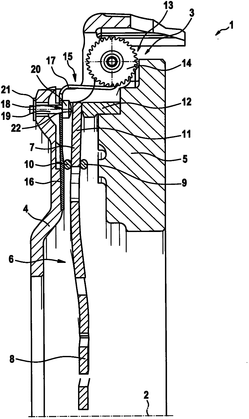
[0030] figure 1 A partial section of an exemplary embodiment of a friction clutch 1 along its axis of rotation 2 is shown, only one half with the compensating adjustment device 3 being shown. The friction clutch 1 is formed by a clutch housing 4 in which a pressure plate 5 is received in a rotationally fixed and axially displaceable manner by means of an energy store, not visible in this section. Furthermore, the lever system 6 is accommodated in the clutch housing 4 as a disk spring 7 which has disk spring tongues 8 radially on the inside, which are axially controlled by a disengaging system not shown. supporting. The illustrated exemplary embodiment is a pressure friction clutch 1 which is disengaged when the Belleville spring tongue 8 is acted upon by pressure. For this purpose, the disk spring 7 is pivotably supported on the clutch housing by means of two wire loops 9 , 10 via a rivet, not shown, which presses the two wire loops 9 , 10 against each other, forming a doub...


PUM


Abstract

Disclosed is a friction clutch which comprises a path-controlled adjusting device and in which wear of the friction linings is compensated by compensating a first distance created between a contact plate and a lever system by twisting a ramp system located between the contact plate and the lever system by means of a spindle having a pinion, said first distance being compensated when it is determined that a second predefined distance between a pressure plate and the clutch housing exceeds a predefined value while the lever system applies the maximum force to the pressure plate. The ramp system is twisted while the lever system relieves the pressure from the pressure plate, and the pressure plate is moved by means of the energy stores that are effective between the pressure plate and the clutch housing by having a pawl twist the pinion. In this process, the pawl slides along the pinion during a lifting movement and positively locks therewith when wear has been identified. In order to prevent the pinion from being twisted because of the friction generated between the pawl and the pinion, at least one catch is connected to the pinion.

Description

technical field [0001] The invention relates to a friction clutch having a pressure plate and a pressure plate which is axially limitedly displaceable relative to the pressure plate and which is loaded by a lever system for establishing a friction fit with respect to the friction plates of the clutch disc, wherein , according to the wear, the compensation adjustment of the friction clutch is carried out through the compensation adjustment of the lever system. Background technique [0002] Friction clutches with compensating adjustment devices are already known. Such a compensation adjustment can be performed, for example, in a force-controlled manner. In this case, unfavorable changes in the contact force of a lever system acting on a pressure plate of the friction clutch, for example a disc spring, due to wear, are detected and a compensating adjustment is carried out as a function of the contact force. As an alternative, the error distance between the clutch housing and ...

Claims


Application Information

Patent Timeline
Patent Type & Authority Applications(China)
IPC IPC(8): F16D13/75
CPCF16D13/757
Inventor M·施奈德G·阿纳特E·胡梅尔
Owner SCHAEFFLER TECH AG & CO KG
Why Eureka
Try Eureka