Water pocket using a percolation well for the in-ground storage of percolated rainwater

A technology of seepage pipes and rainwater, which is applied in waterway systems, sewage removal, water supply devices, etc., can solve problems such as inability to remove, rainwater infiltration, and infiltration, and achieve the effect of easy and sustainable management.

Inactive Publication Date: 2011-07-27
任哲雄
View PDF7 Cites 15 Cited by
  • Summary
  • Abstract
  • Description
  • Claims
  • Application Information

AI Technical Summary

Problems solved by technology

[0007] Generally speaking, in the structure where the bottom surface of the sewer storage well is directly connected to the seepage pipe, the rainwater flowing into the sewer storage well is mixed with various ground garbage or foreign objects. However, foreign matter will accumulate inside the seepage pipe or block the through hole of the seepage pipe. Although small foreign matter can penetrate the through hole, it cannot penetrate into the soil, and it will accumulate more and more in the filter layer around the seepage pipe.
[0008] If the accumulation of foreign matter is formed for a long time, the rainwater will not be able to penetrate into the soil through the seepage pipe, and the seepage pipe will not be able to perform its normal function
In order to prevent the occurrence of this problem, Japanese Patent Laid-Open No. 2007-231734 discloses that the upper end of the seepage pipe is equipped with a filter screen structure that prevents foreign matter from flowing in, but this filter screen alone cannot prevent fine foreign matter from passing through. When the fine foreign matter accumulates in the through hole of the seepage pipe and the surrounding filter layer, it cannot be removed, so there is a problem that it cannot be used for a long time

Method used


Image

  • Water pocket using a percolation well for the in-ground storage of percolated rainwater
  • Water pocket using a percolation well for the in-ground storage of percolated rainwater
  • Water pocket using a percolation well for the in-ground storage of percolated rainwater

Examples


Embodiment Construction

[0025] The present invention and the technical problems achieved by implementing the present invention become clear from the description of the following preferred embodiments. The following examples are just to illustrate the present invention, but not to limit the scope of the present invention. The present invention will be described in detail below with reference to the accompanying drawings.

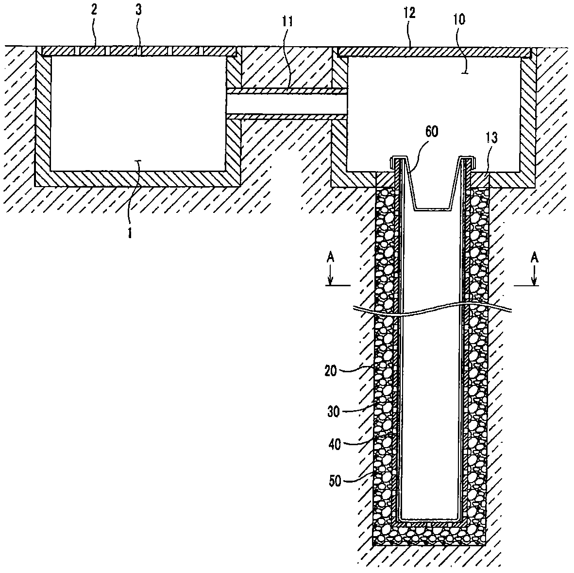
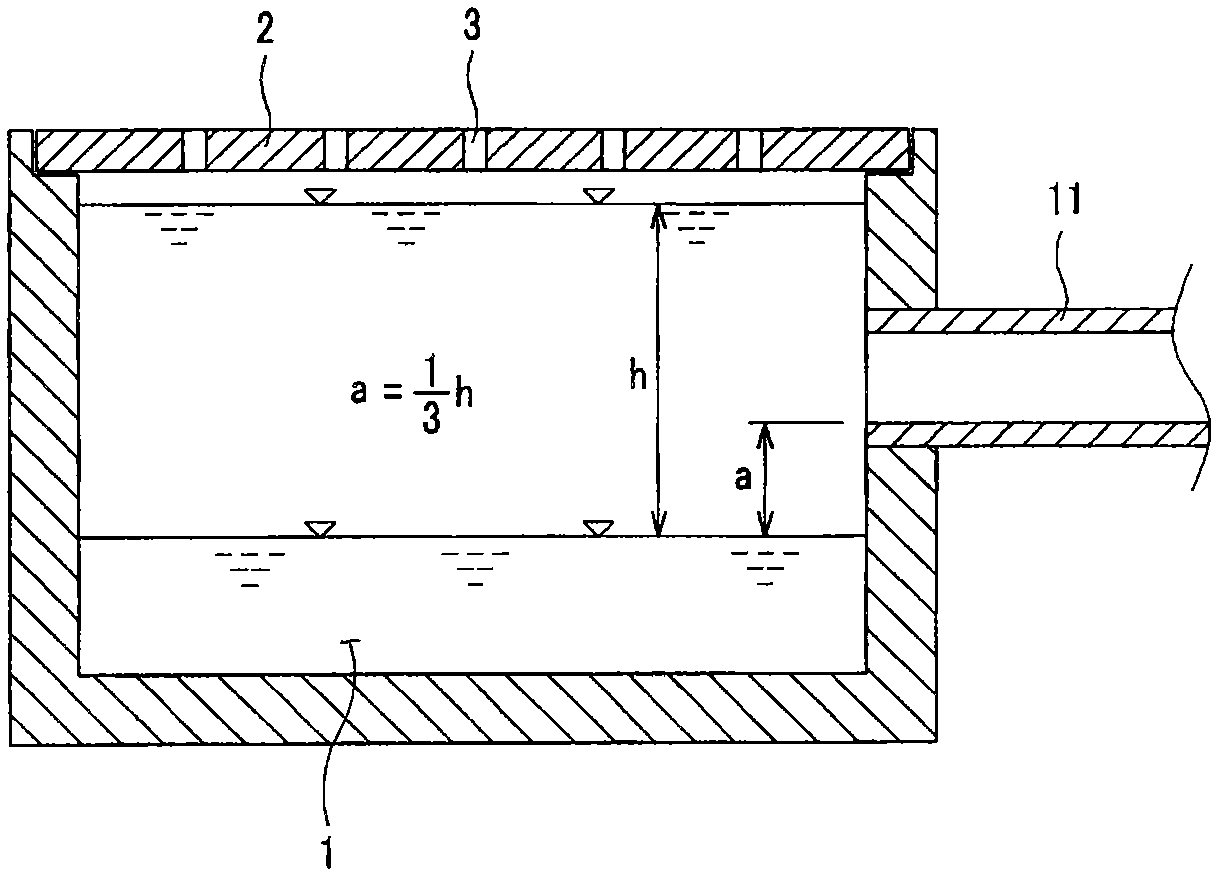
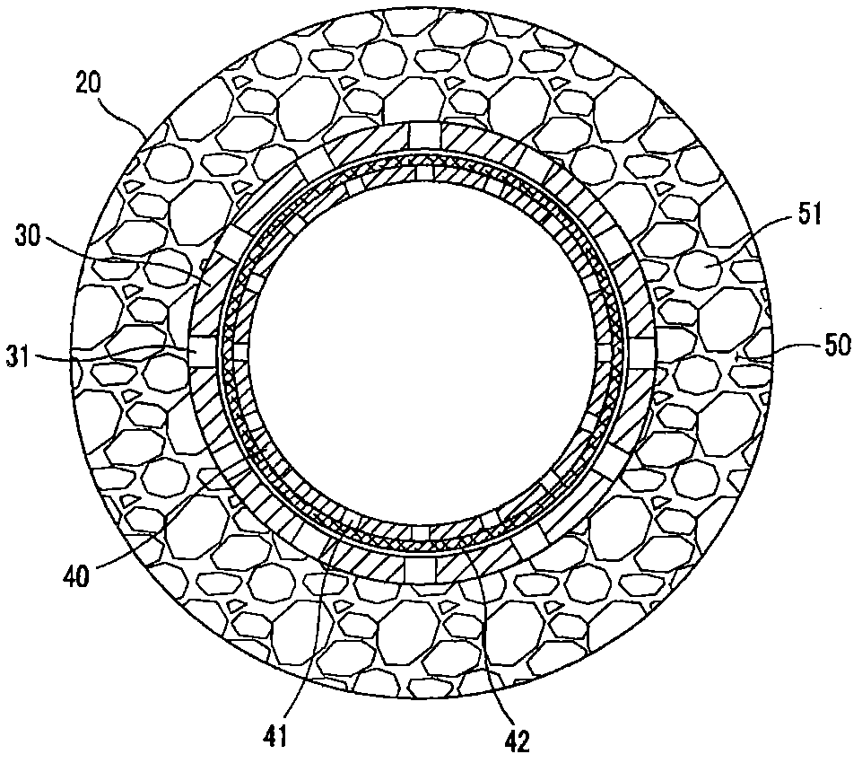
[0026] figure 1 It is a longitudinal sectional view of the water bag provided by the embodiment of the present invention, figure 2 It is an enlarged cross-sectional view of the detailed structure of the connecting pipe provided by the embodiment of the present invention, image 3 yes figure 1 The A-A section diagram, Figure 4 It is an enlarged cross-sectional view of the detailed structure of the seepage tube well provided by the embodiment of the present invention.

[0027] As shown in the embodiments of the present invention, the water bladder provided by the present invent...


PUM


Abstract

The present invention relates to a water pocket capable of preventing the reverse flow of rainwater from a drain by reducing the rate of water outflow, by percolating a portion of the rainwater, which concentrates at a sump of the drain during flooding when the water level suddenly swells, deep underground through the water pocket. In order to achieve the above aim, a water pocket for preventing the reverse flow of rainwater from a drain according to the present invention comprises: a rainwater inlet tank connected to a side of a drain sump via a connecting pipe, into which rainwater collected at the sump is admitted through the connecting pipe; a percolation well formed in-ground below the floor of the rainwater inlet tank; a first perforated pipe having a cylindrical shape and a plurality of through-holes defined in the periphery thereof, and which is inserted within the percolation well to define a space between the walls of the percolation well; a second perforated pipe having a cylindrical shape and a plurality of through-holes defined in the periphery thereof, which is inserted within the first perforated pipe and has a non-woven fabric coupled tightly to an outer portion thereof to filter impurities; a filter layer filled with aggregate in a space between the percolation well and the first perforated pipe; and a filter mesh fastened so as to block the top of the first perforated pipe, wherein rainwater is discharged through only the outlet of the sump during normal flow conditions, and during abnormal flow conditions, rainwater that flows into the rainwater inlet tank through the connecting pipe is percolated and stored in the ground through the first and second perforated pipes and the filter layer.

Description

technical field [0001] The present invention relates to the water bag (Water Pocket) that adopts the permeable pipe well that infiltrates and stores rainwater into the soil. Rainwater is infiltrated and stored in the soil, thereby slowing down the outflow of rainwater and preventing the flooding of the river, using the water bladder of the seepage pipe well that infiltrates and stores rainwater in the soil. Background technique [0002] Recently, cities, especially low-lying areas, often suffer from unpredictable flood disasters due to frequent torrential rains or heavy rains during the rainy season or typhoons. One of the main reasons for causing rain floods or large amounts of water in low-lying areas of the city is that the drainage function of rivers or sewers is not perfect, causing rainwater to overflow beyond urban drainage facilities, resulting in flooding of low-lying areas and rivers. [0003] Recently, due to the development of industrialization, most roads in ci...

Claims


Application Information

Patent Timeline
Patent Type & Authority Applications(China)
IPC IPC(8): E03F1/00E03F5/00E03F5/10
CPCE03F1/002Y02A10/30Y02A20/40E03F5/042E03F5/101E03F5/105E03F5/14
Inventor 任哲雄
Owner 任哲雄
Why Eureka
Try Eureka