
Hot-pressing sticking mechanism

A technology of sticking and thermal pressing head, which is applied in the field of flat panel display manufacturing equipment, can solve the problems of large instantaneous impact and inaccurate control of the pressing pressure of the thermal pressing head, and achieve the effects of avoiding impact, ensuring safety and improving the pass rate

Active Publication Date: 2011-07-27
苏州凯蒂亚半导体制造设备有限公司
View PDF5 Cites 11 Cited by
  • Summary
  • Abstract
  • Description
  • Claims
  • Application Information

AI Technical Summary

Problems solved by technology

[0005] The purpose of the present invention is to provide a hot pressing application mechanism to solve the problems of inaccurate control of the pressing pressure of the hot pressing head and large instantaneous impact of the existing hot pressing applying mechanism

Method used


Image

  • Hot-pressing sticking mechanism
  • Hot-pressing sticking mechanism
  • Hot-pressing sticking mechanism

Examples


Embodiment

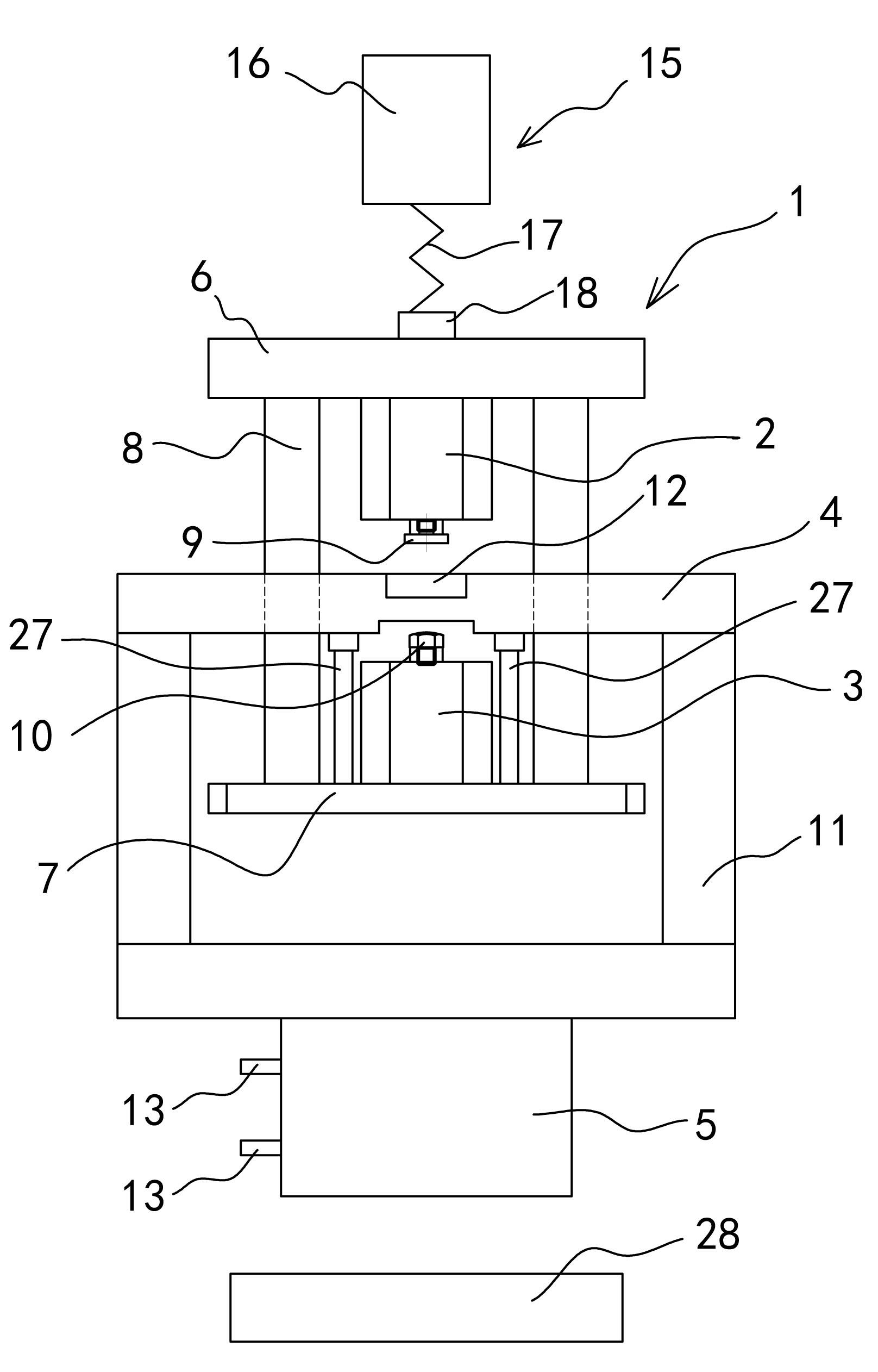
[0023] Example: see attached image 3 , 4 Shown:

[0024] A hot pressing application mechanism, comprising a supporting frame 1, an upper pressing cylinder 2, a lower supporting cylinder 3, a middle balance plate 4, a hot pressing head 5 and a table top 28, the supporting frame 1 is mainly composed of an upper supporting beam 6, a lower supporting beam The supporting beam 7 and two vertical columns 8 connected between the upper supporting beam 6 and the lower supporting beam 7 are formed; 1 is slidingly connected in the up and down direction; the upper pressing cylinder 2 is set upward and downward by the upper support beam 6, and its piston rod action end 9 is aligned with the top surface of the middle balance plate 4, and the lower supporting cylinder 3 is supported by the lower The beam 7 is arranged upwards, and its piston rod action end 10 is aligned with the bottom surface of the middle balance plate 4; the thermal pressure head 5 is arranged below the support frame 1,...


PUM


Abstract

The invention discloses a hot-pressing sticking mechanism, which is characterized by comprising a supporting frame, an upper pressing cylinder, a lower supporting cylinder, a middle balance plate and a hot-pressing head, wherein the supporting frame mainly comprises an upper supporting beam, a lower supporting beam and two vertical upright posts which are connected between the upper supporting beam and the lower supporting beam; the middle balance plate is arranged in parallel between the upper supporting beam and the lower supporting beam; the upper pressing cylinder is arranged on the upper supporting beam downwards, and a piston rod acting end is aligned with the top surface of the middle balance plate; the lower supporting cylinder is arranged on the lower supporting beam upwards, and a piston rod acting end is aligned with the bottom surface of the middle balance plate; and the hot-pressing head is arranged below the supporting frame and is fixedly connected with the middle balance plate through a bracket. The support of the lower supporting cylinder counters dead weight of the middle balance plate and the hot-pressing head connected to the middle balance plate, so that pressure can be accurately applied to the upper pressing cylinder; moreover, the lower supporting cylinder has buffering function and avoids impact to the greatest degree.

Description

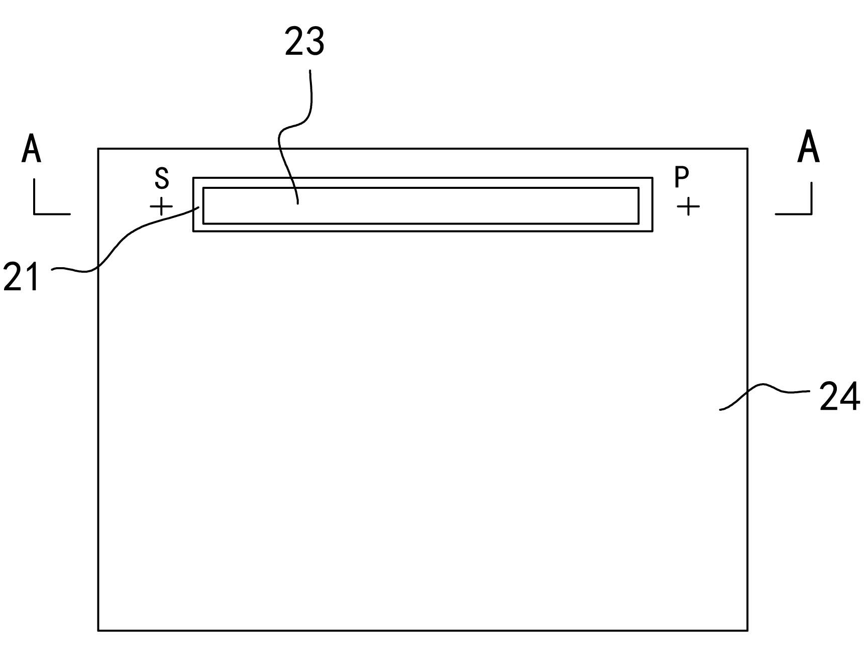
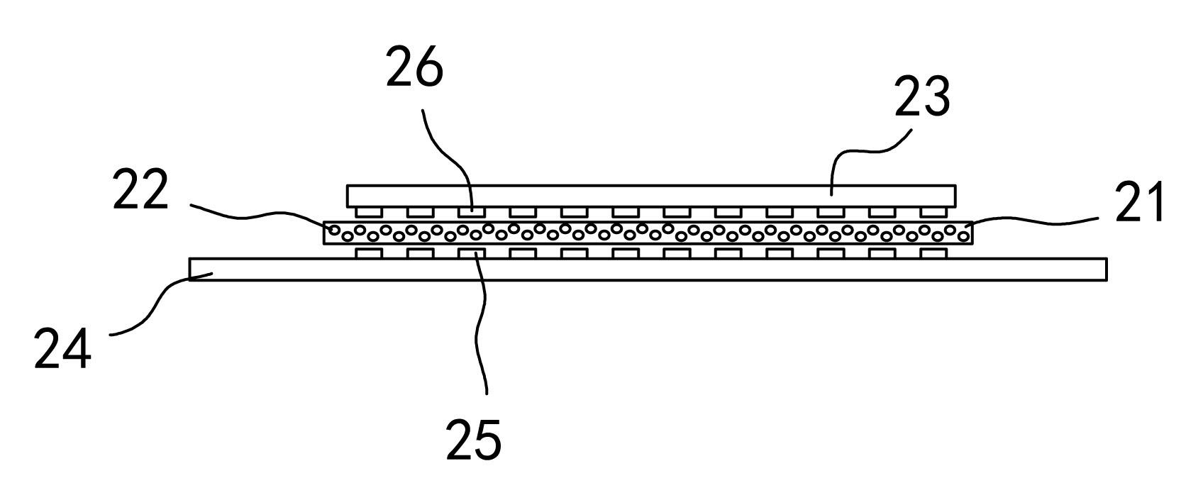
technical field [0001] The invention relates to flat-panel display manufacturing equipment, in particular to a hot-press application mechanism in a COG, FOG or COF hot-press device. The COG (that is, CHIP ON GLASS) refers to the mounting process that uses the ACF film to directly bind the chip on the LCD screen through hot pressing. The FOG (that is, FILM ON GLASS) refers to the use of the ACF film to directly bind A mounting process in which a flexible circuit board is bound on a liquid crystal display, and the COF (ie CHIP ON FILM) refers to a mounting process in which an ACF film is used to directly bind a chip to a flexible circuit board through thermal pressing. Background technique [0002] In the manufacturing process of flat panel displays (FPD) such as LCD (liquid crystal) and PDP (plasma), it is an important task to correctly assemble the drive circuits such as chip IC or flexible circuit board FPC to the drive terminal area of ​​the liquid crystal display. Its pu...

Claims


Application Information

Patent Timeline
Patent Type & Authority Applications(China)
IPC IPC(8): G02F1/13H01L21/603
Inventor 陈华轩景建平唐志稳朱晓伟
Owner 苏州凯蒂亚半导体制造设备有限公司
Learn More