midwifery instrument
A midwifery instrument and air bag technology, applied in the field of medical devices, can solve problems such as the inability to accurately control the diameter of the bionic air bag, inability to ensure the pain of pregnant women, and reducing the probability of cesarean section, so as to reduce the infection of bacteria and the like, the structure is simple, and the pain is reduced. Effect
- Summary
- Abstract
- Description
- Claims
- Application Information
AI Technical Summary
Problems solved by technology
Method used
Image
Examples
no. 1 example
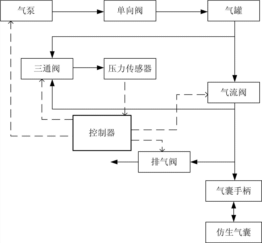
[0036] see figure 1 , the first embodiment of the present invention provides a midwifery instrument, which includes an air pump, a one-way valve, an air tank, an airflow valve, an airbag handle, an imitation airbag, an exhaust valve, a pressure sensor, a three-way valve, a control The device and the pipeline connecting the components in the midwifery instrument. The air pump communicates with the air tank through a pipeline, and inflates the air tank. The air tank is connected to the airbag handle through an inflation pipeline, the airflow valve is installed on the inflation pipeline, and the air tank is inflated to the imitation airbag through the airflow valve and the airbag handle in sequence. The exhaust valve is installed between the air bag handle and the air flow valve. The pressure sensor is installed between the air tank and the air bag handle, and is used to measure the gas pressure in the air tank and the bionic air bag before and after each inflation of the bioni...
no. 2 example
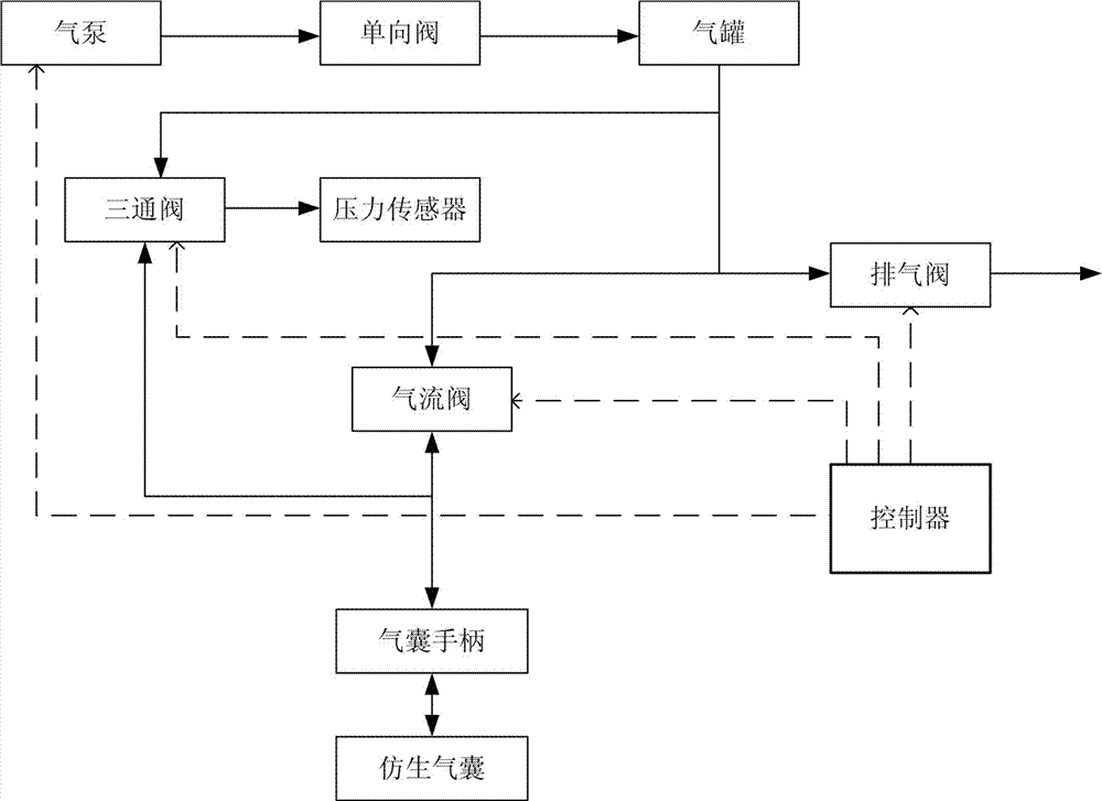
[0046] see figure 2 , the second embodiment of the present invention provides a midwifery instrument, the structure of the midwifery instrument is basically the same as that of the midwifery instrument provided by the first embodiment, the difference is that the exhaust valve is installed on the air between the tank and the airflow valve. Specifically, an exhaust pipeline is provided on the inflation pipeline between the air flow valve and the air tank, and the exhaust valve is installed on the exhaust pipeline.
[0047] The method for controlling the diameter of the above-mentioned bionic air bag provided in this embodiment is basically the same as the method for controlling the diameter of the bionic air bag in the midwifery instrument provided in the first embodiment, except that:
[0048] Step 3, the controller continues to close the airflow valve for a period of time, the air tank stops inflating the bionic airbag, and the bionic airbag maintains its predetermined diame...
no. 3 example
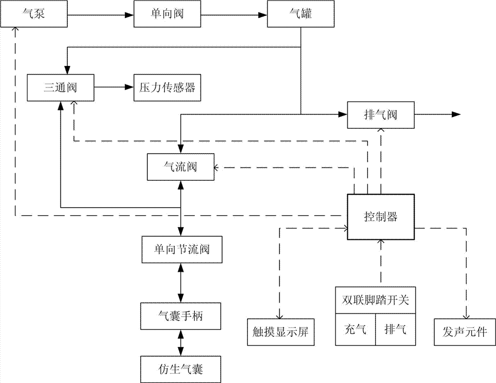
[0050] see image 3 , the third embodiment of the present invention provides a midwifery instrument, the structure of the midwifery instrument is basically the same as that of the midwifery instrument provided by the second embodiment, the difference is that the midwifery instrument also includes a control inflation The amount of one-way throttle valve, the one-way throttle valve is installed on the inflation pipeline between the airflow valve and the airbag handle, the airbag handle is respectively connected with the airflow through the one-way throttle valve The valve communicates with the three-way valve. Specifically, the airflow valve and the one-way throttle valve are sequentially installed on the inflation pipeline along the direction from the air tank to the airbag handle, and the one-way throttle valve and the airflow valve An air inlet pipe is provided on the inflatable pipe between them, and the air inlet pipe is connected with an inlet end of the three-way valve f...
PUM
 Abstract
Description
Claims
Application Information
 - R&D
- Intellectual Property
- Life Sciences
- Materials
- Tech Scout
- Unparalleled Data Quality
- Higher Quality Content
- 60% Fewer Hallucinations
Browse by: Latest US Patents, China's latest patents, Technical Efficacy Thesaurus, Application Domain, Technology Topic, Popular Technical Reports.
© 2025 PatSnap. All rights reserved.Legal|Privacy policy|Modern Slavery Act Transparency Statement|Sitemap|About US| Contact US: help@patsnap.com


