Monitoring module for SF6 inflation and deflation recovery device and flowmeter deviation correction method
A recovery device and monitoring module technology, applied in the direction of indirect mass flowmeter, measuring device, measuring fluid pressure, etc., can solve the problems of monitoring result error and achieve the effect of gas stability
- Summary
- Abstract
- Description
- Claims
- Application Information
AI Technical Summary
Problems solved by technology
Method used
Image
Examples
Embodiment 1
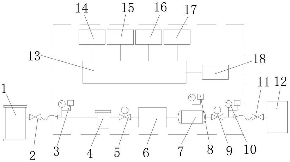
[0037] Such as figure 1 shown, for SF 6 The monitoring module of the inflation and recovery device includes a gas pipeline, and the two ends of the gas pipeline are respectively provided with a GIS interface and a recovery equipment interface. The chamber is connected, and the recovery device interface is located at the right end of the gas pipeline, and is connected to the recovery device 12 through the second manual valve 11 .
[0038] A first pressure sensor 3, a filter 4, a first solenoid valve 5, a flow meter 6, a calibration container 7 and a calibration container pressure set on the calibration container 7 are arranged in sequence from left to right between the GIS interface 2 and the recovery device 12 The detection structure, the second solenoid valve 9 and the third pressure sensor 10, the above-mentioned components are all prior art, the specific structure of each component will not be described here, and only the specific function and working state of each compone...
Embodiment 2
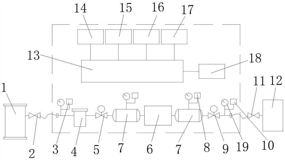
[0051] The difference between this embodiment and Embodiment 1 is that in Embodiment 1, a calibration container 7 is provided on the right side of the flow meter 6, and the flow rate and the deviation correction coefficient can be calculated by the flow rate of the flow meter 6 and the pressure value of the calibration container 7 , to realize the correction of the flow meter 6 in the gas recovery operation. And in this embodiment, if figure 2As shown, a calibration container 7 is added between the flow meter 6 and the first electromagnetic valve 5. In the same way as in Embodiment 1, the flow meter 6 can be adjusted in the gas flow through the flow meter 6 and the calibration container 7 on the left side of the flow meter 6. Correction during inflation operation. At this time, both the first solenoid valve 5 and the second solenoid valve 9 are valves located downstream of the flow meter 6 in use.
[0052] Of course, in other embodiments, the calibration container 7 can als...
Embodiment 3
[0054] The difference between this embodiment and Embodiment 1 is that in Embodiment 1, the calibration container detection structure is directly installed on the calibration container 7 . In this embodiment, however, the calibration container detection structure is arranged between the calibration container 7 and the second solenoid valve 9 , and the calibration container detection structure communicates with the flow meter 6 through the gas pipeline.
PUM
 Abstract
Description
Claims
Application Information
 - R&D
- Intellectual Property
- Life Sciences
- Materials
- Tech Scout
- Unparalleled Data Quality
- Higher Quality Content
- 60% Fewer Hallucinations
Browse by: Latest US Patents, China's latest patents, Technical Efficacy Thesaurus, Application Domain, Technology Topic, Popular Technical Reports.
© 2025 PatSnap. All rights reserved.Legal|Privacy policy|Modern Slavery Act Transparency Statement|Sitemap|About US| Contact US: help@patsnap.com


