
Contactor

A contactor, moving contact technology, applied in relays, electromagnetic relays, electromagnetic relay details, etc., to achieve the effect of reducing the number of parts

Active Publication Date: 2014-08-13
SCHNEIDER ELECTRIC IND SAS
View PDF4 Cites 0 Cited by
  • Summary
  • Abstract
  • Description
  • Claims
  • Application Information

AI Technical Summary

Problems solved by technology

[0005] Although the current contactor can basically realize the bypass function, there is still room for improvement

Method used


Image

  • Contactor
  • Contactor
  • Contactor

Examples


Embodiment Construction

[0031] Embodiments of the present invention will be specifically described below with reference to the drawings.

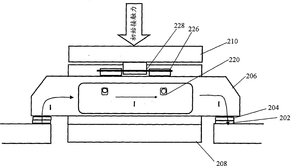
[0032] figure 1 It is a front view of an embodiment of the contactor of the present invention. The contactor includes a housing 200 (in figure 1 not shown in), the fixed contact 202, the movable contact 204, the movable contact finger 206 electrically connected with the movable contact, the U-shaped magnetic circuit 208 surrounding the movable contact finger, and the U-shaped magnetic circuit opening The plate-shaped magnetic circuit 210 is opposite and separated by an air gap. The movable contact finger 206 extends across the U-shaped magnetic circuit along a plane of symmetry of the U-shaped magnetic circuit. The movable contact 204 is disposed below both ends of the movable contact finger 206 . The fixed contact 202 is opposite to the movable contact 204 .

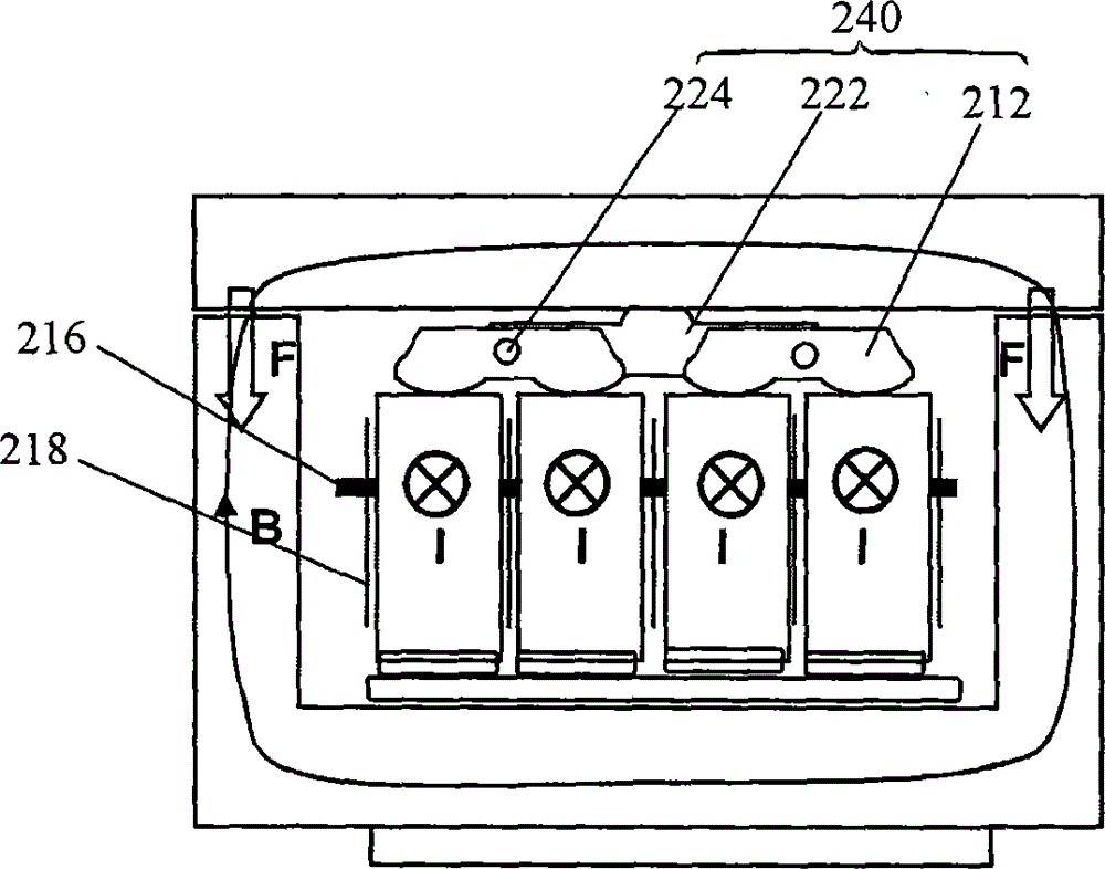
[0033] figure 2 is a side view of the contactor. from figure 2 It can be seen that there are f...


PUM


Abstract

A contactor includes a housing, a fixed contact (202), a movable contact (204), a movable contact finger (206) conductively connected to the movable contact, and a U-shaped magnetic circuit surrounding the movable contact finger. (208), a plate-shaped magnetic circuit (210) opposite to the U-shaped magnetic circuit opening and separated by an air gap. The movable contacts are arranged at both ends of the movable contact finger, and the fixed contacts are arranged opposite to the movable contacts. , wherein there are at least two movable contact fingers, which are arranged together substantially in parallel and are insulated from each other. The contactor complies with the "Class 2" standard of IEC 60947-4 and no contact welding occurs during test runs with the expected current.

Description

technical field [0001] The present invention relates to contactors, in particular to high current contactors used in soft starters. Background technique [0002] In soft starter products, a dedicated contactor is typically used to bypass the rectifier (SCR) after the vehicle has fully started. Bypassing the rectifier prevents power from being dissipated as heat in the rectifier chip. The contactor is opened (open operation) during starting or deceleration (braking) so that the rectifier unit controls the motor vehicle, and in normal stable operation after the SCR is fully fired, the contactor is closed (open operation) operate). [0003] Commonly used contactors include single-pole contactors, which operate a single movable contact with a DC coil (eg, Ghisalba) or AC coil magnetic circuit (eg, Simens); and multi-pole contactors, whose contacts are connected in parallel. Form a single pole (eg, Rockwell). [0004] The combination of U-shaped magnetic circuit and plate-sha...

Claims


Application Information

Patent Timeline
Patent Type & Authority Patents(China)
IPC IPC(8): H01H50/54H01H50/16
Inventor 伯纳德·比扎德
Owner SCHNEIDER ELECTRIC IND SAS
Learn More