
Electrical connector and manufacturing method thereof

An electrical connector and a manufacturing method technology, which are applied in the field of electrical connectors with elastic butt joints and their manufacturing, can solve the problem of pressure loss and deformation of large U-shaped deformation parts of conductive terminals, unstable focus points of conductive terminals, and inability to protect large U-shaped Deformation parts and other problems can be achieved to optimize manufacturing performance and avoid instability of the focus point

Active Publication Date: 2011-07-27
FOXCONN (KUNSHAN) COMPUTER CONNECTOR CO LTD +1
View PDF1 Cites 1 Cited by
  • Summary
  • Abstract
  • Description
  • Claims
  • Application Information

AI Technical Summary

Problems solved by technology

Among them, the preliminary preparation of the conductive terminals is a process of stamping the metal strip into the shape of several terminals arranged side by side and winding them into a coil. During the winding process, special attention should be paid to the protection of the formed terminals. If the terminals and their materials The pressure loss and deformation of the terminal caused by poor design or manufacturing process will cause hidden dangers to the assembly and performance of the electrical connector in the later stage
[0003] Please refer to an electrical connector shown in US Patent Publication No. 20090137162, and especially refer to Figure 3 of the patent, the electrical connector includes an insulating body with a plurality of terminal grooves and a plurality of conductive terminals horizontally installed in the terminal grooves, The conductive terminal has a large U-shaped deformation portion located at the upper end of the main body and bent toward the inside of the main body, and the lower end of the conductive terminal is provided with a welding portion bent toward the outer side of the main body. When the conductive terminal is rolled into a disk, the small welding portion Not only can it not protect the large U-shaped deformation part, but also make the contact point of the conductive terminal very unstable, which may easily cause pressure loss and deformation of the large U-shaped deformation part of the conductive terminal

Method used


Image

  • Electrical connector and manufacturing method thereof
  • Electrical connector and manufacturing method thereof
  • Electrical connector and manufacturing method thereof

Examples


Embodiment Construction

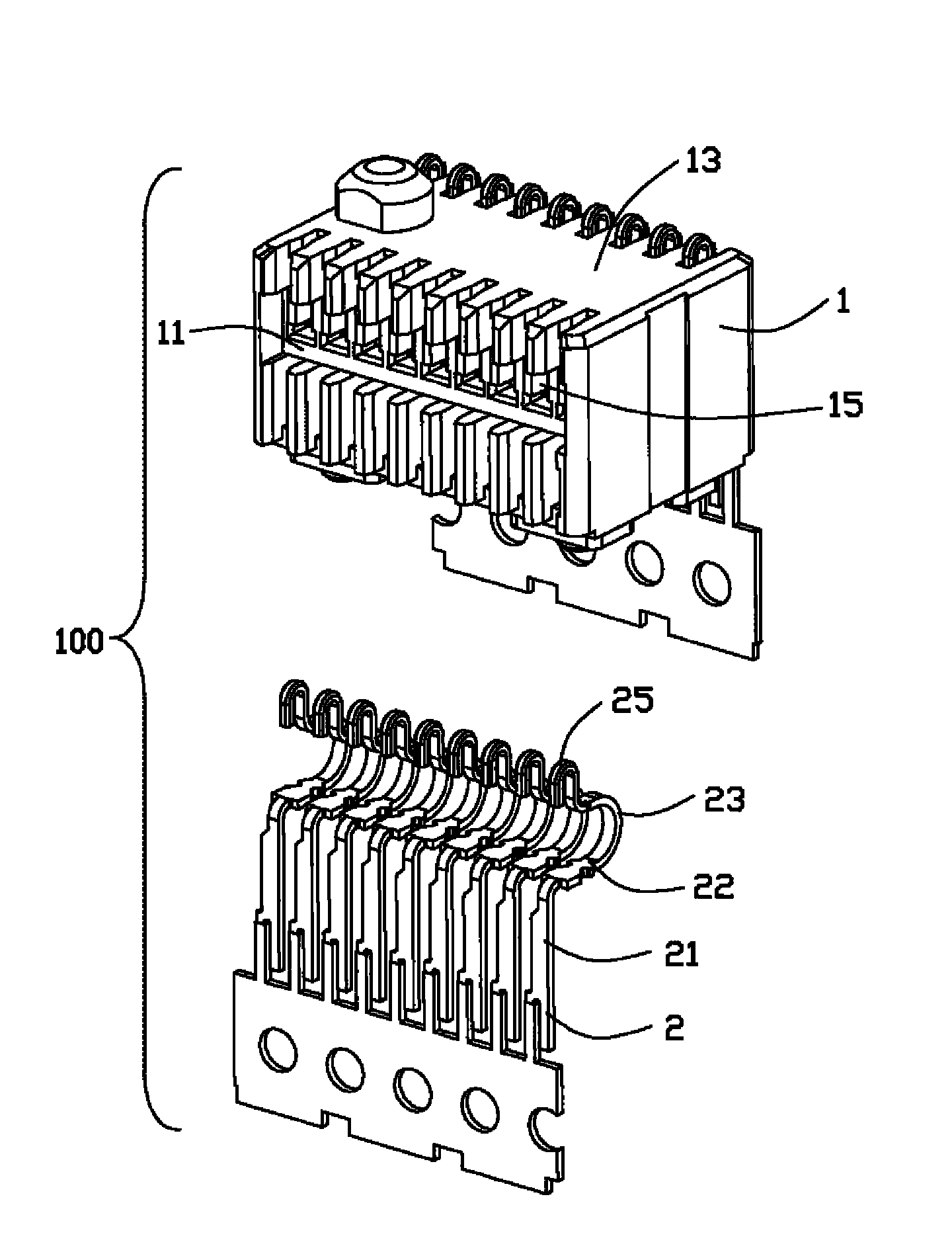
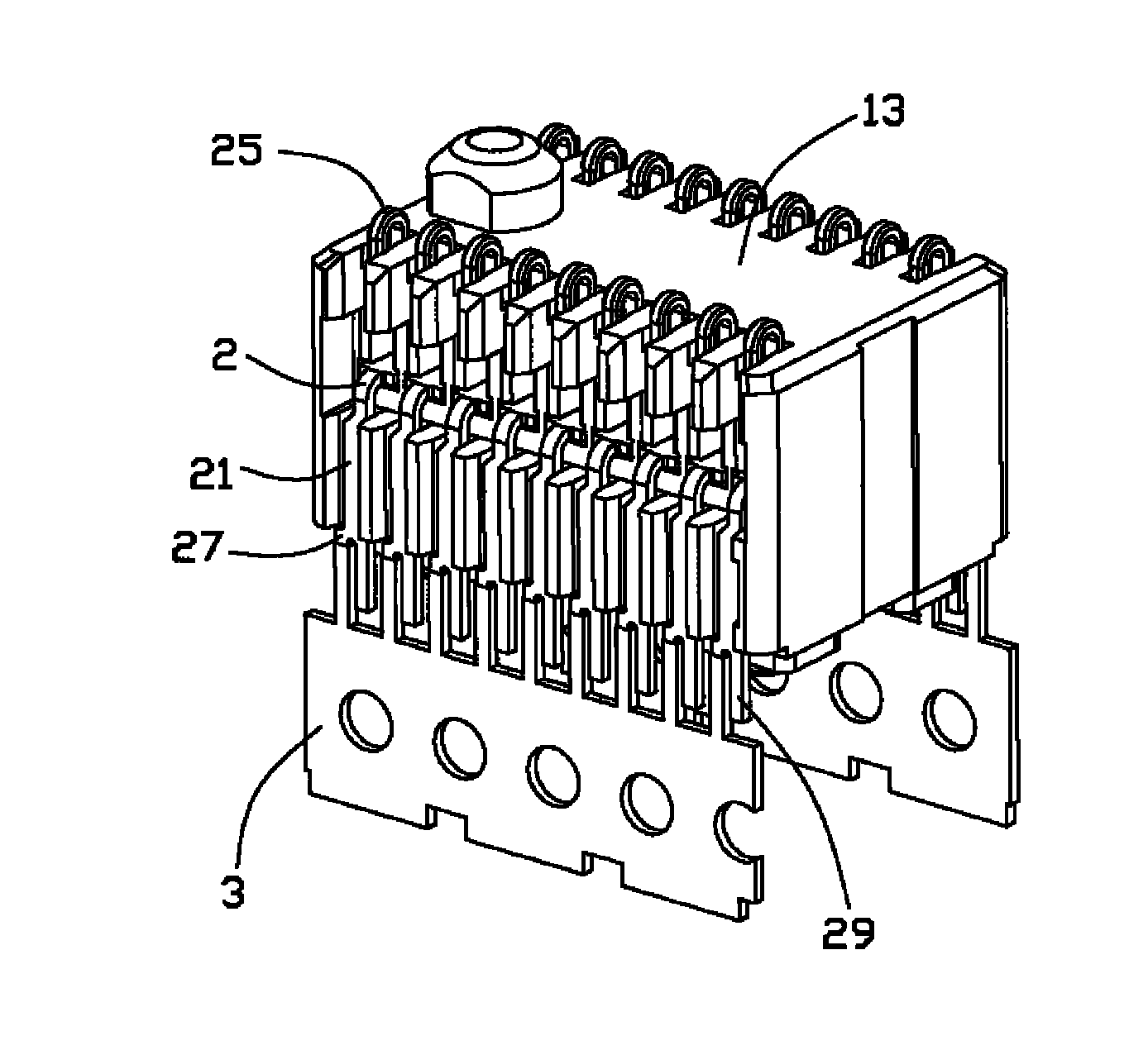
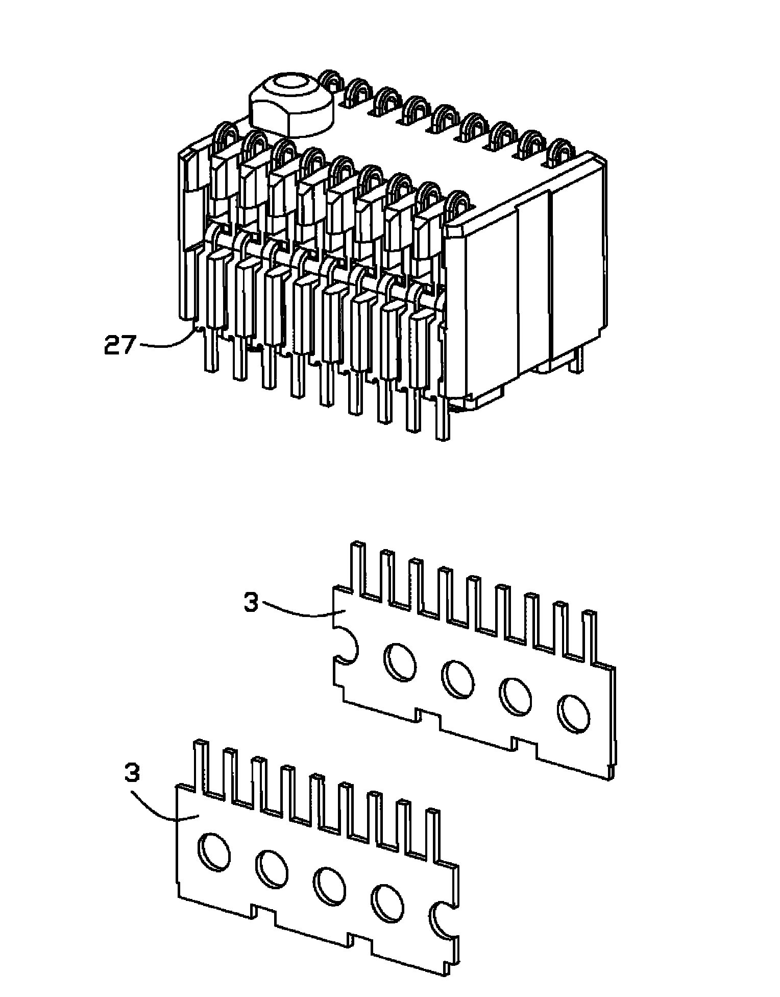
[0013] see Figure 1 to Figure 4 , these drawings sequentially describe the manufacturing and assembling process and overall structure of the electrical connector 100 of the present invention.

[0014] see figure 1 The electrical connector 100 includes an insulating body 1 having a front wall 11 and a top wall 13 , and the insulating body 1 is concavely provided with a terminal groove 15 communicating with the top wall 13 from the front wall 11 to the interior of the insulating body 1 . The plurality of conductive terminals 2 include a vertically elongated body portion 21 , a U-shaped deformation portion 23 protruding from the upper end of the body portion 21 , and a crimping portion 25 located at the end of the U-shaped deformation portion 23 .

[0015] see figure 2 , the conductive terminal 2 also includes a strip connection end 27 and a main body extension end 29 arranged side by side at the lower end of the main body 21, the strip 3 is connected with the strip connectio...


PUM


Abstract

The invention discloses an electrical connector and a manufacturing method thereof. The electrical connector comprises an insulating body and a plurality of conductive terminals accommodated in the insulating body, wherein terminal grooves are reserved on the front wall surface of the insulating body in a concave way; each conductive terminal comprises a main body part, a strip connecting end anda main body part extending end, wherein the main body part is extended in an up-and-down direction; the strip connecting end and the main body part extending end are arranged at the lower end of the main body part side by side; the main body part extending end is extended downward continuously along the main body part; the conductive terminals are assembled behind the insulating body; and the main body part extending end is bent to form a welding end which is vertical to the front wall surface. The assembled bent conductive terminal welding ends avoid a phenomenon that an acting point is instable when the conductive terminals are rolled to form a coil; the plane between the main body part and a strip can serve as a rolled basal plane effectively; and the manufacturing performance of products optimized without influencing the overall structure of the electrical connector.

Description

【Technical field】 [0001] The invention relates to an electrical connector and a manufacturing method thereof, in particular to an electrical connector with an elastic butt end and a manufacturing method thereof. 【Background technique】 [0002] As a miniaturized and widely used electronic component, electrical connectors are currently produced by automated assembly. The manufacturing process of electrical connectors generally includes forming an insulating body and a number of conductive terminals housed in the insulating body, and introducing them into later stages. The automatic assembly line completes the assembly. Among them, the preliminary preparation of the conductive terminals is a process of stamping the metal strip into the shape of several terminals arranged side by side and winding them into a coil. During the winding process, special attention should be paid to the protection of the formed terminals. If the terminals and their materials The pressure loss and def...

Claims


Application Information

Patent Timeline
Patent Type & Authority Applications(China)
IPC IPC(8): H01R13/22H01R13/40H01R43/20
Inventor 朱宇
Owner FOXCONN (KUNSHAN) COMPUTER CONNECTOR CO LTD
Learn More