Screw for composite board

a composite board and screw technology, applied in the direction of screws, threaded fasteners, fastening means, etc., can solve the problems of uneven raised bumps on the board surface, affecting the finished appearance and structural safety of the composite board, and limited space, so as to achieve a safe structure and a pleasing finished appearance

Inactive Publication Date: 2007-03-15
KWANTEX RES
View PDF9 Cites 19 Cited by
  • Summary
  • Abstract
  • Description
  • Claims
  • Application Information

AI Technical Summary

Benefits of technology

[0009] Therefore, the object of the present invention is to provide a screw for use in a composite board that is capable of forming a space sufficient for storing composite board materials displaced by the screw, and that can prevent the formation of a “volcano” on the surface of the board and / or cracks, in order to maintain a neat finished appearance and a safe structure for the composite board.

Problems solved by technology

Since composite board does not have the fiber structure of wood, materials displaced by a screw during installation tend to move up along the shank of the screw, thereby resulting in an irregular raised bump on the board surface, which is commonly referred to as a “volcano,” or even cracks on edges of the board around where the screw is installed.
The “volcano” and cracks greatly affect the finished appearance and structural safety of the composite board.
This space is very limited and therefore, the composite board is still vulnerable to the formation of a “volcano” and / or cracks on edges of the board around where the screw is installed.
Taking into account the size of the second conventional screw 2 and the size of the hole that surrounds the unthreaded section 24, if the second conventional screw 2 is to be completely driven into the composite board, there would not be enough space for storing all of the displaced materials, so that the second conventional screw 2 is still incapable of suppressing the formation of a “volcano” on the surface of the board or cracks on edges of the board around where the screw is installed.

Method used


Image

  • Screw for composite board
  • Screw for composite board
  • Screw for composite board

Examples


Embodiment Construction

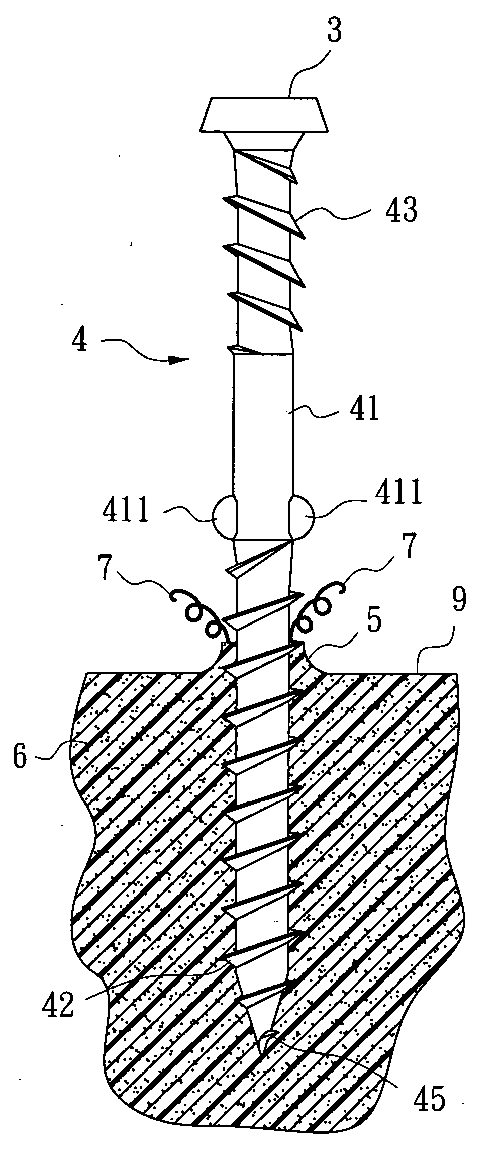
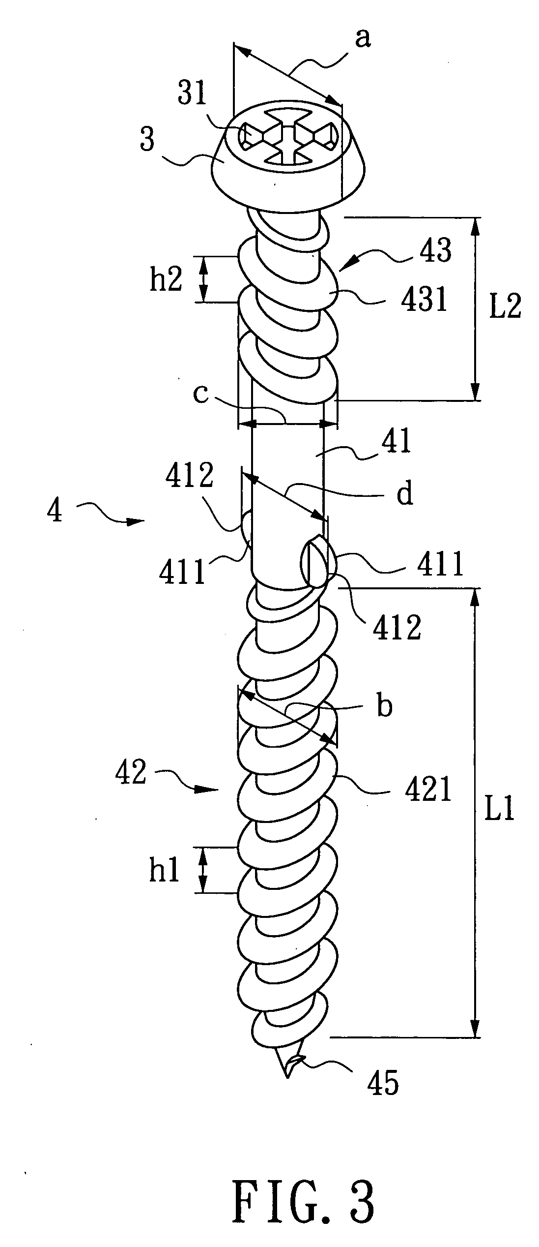
[0017] As shown in FIG. 3, the preferred embodiment of a screw according to the present invention includes a head 3, and a shank 4 connected to the head 3.

[0018] The head 3 has a head diameter (a), and a bit-receiving recess 31 that can be of any shape, such as the standard Phillips, Robertson, Torx, and Hex, or the shape as illustrated in FIG. 3 for this preferred embodiment, etc. However, the actual shape of the bit-receiving recess 31 is not a feature of this invention, so it should not limit the scope of this invention.

[0019] The shank 4 includes a lower threaded section 42, an upper threaded section 43 that is disposed adjacent to the head 3, an unthreaded section 41 that is disposed between the lower threaded section 42 and the upper threaded section 43, and a tip 45 that tapers from the lower threaded section 42. The lower threaded section 42 has a first length (L1), and is formed with a first thread 421 having a first thread diameter (b) smaller than the head diameter (a)....


PUM


Abstract

A screw includes a head, and a shank connected to the head. The shank includes a lower threaded section that is formed with a first thread, and an upper threaded section that is disposed adjacent to the head, and that is formed with a second thread. The second thread is in a reversed orientation relative to the first thread. The shank further includes an unthreaded section that is disposed between the upper threaded section and the lower threaded section, and that is formed with at least one pair of diametrically disposed fins, and a tip that tapers from the lower threaded section. The fins are disposed proximate to the lower threaded section and distal from the upper threaded section.

Description

BACKGROUND OF THE INVENTION [0001] 1. Field of the Invention [0002] This invention relates to a screw, more particularly to a screw for composite board. [0003] 2. Description of the Related Art [0004] Wood is a common material for use in architecture and interior design due to its unique qualities, such as smell, textural pattern, etc. However, ecological and environmental-friendly concepts are widespread nowadays, and many countries have progressively started regulating timber-felling officially. Therefore, wood is increasingly being replaced by composite board that is made from recycled products. In countries such as the United States and Canada, slightly elastic composite board is made by first grinding and then thermal-treating and pressure-treating plastic combined with wood from recycled products. Since composite board does not have the fiber structure of wood, materials displaced by a screw during installation tend to move up along the shank of the screw, thereby resulting in...

Claims


Application Information

Patent Timeline
Patent Type & Authority Applications(United States)
IPC IPC(8): F16B35/04
CPCF16B5/0275F16B25/0031F16B25/0057F16B2033/025F16B25/0089F16B25/10F16B35/041F16B25/0063
Inventor LIN, CHAO-WEI
Owner KWANTEX RES
Why Eureka
Try Eureka