Reactivity control rod for core

a technology of reactivity control rod and core, which is applied in the direction of nuclear reactors, nuclear elements, greenhouse gas reduction, etc., can solve the problems of deteriorating the economics of the reactor, difficult to avoid an accident, and increased cost of manufacturing the reactor system, so as to reduce the heat value dispersed, secure prevent the leakage of liquid metal, and improve the effect of heat efficiency

Inactive Publication Date: 2006-11-21
KK TOSHIBA
View PDF17 Cites 20 Cited by
  • Summary
  • Abstract
  • Description
  • Claims
  • Application Information

AI Technical Summary

Benefits of technology

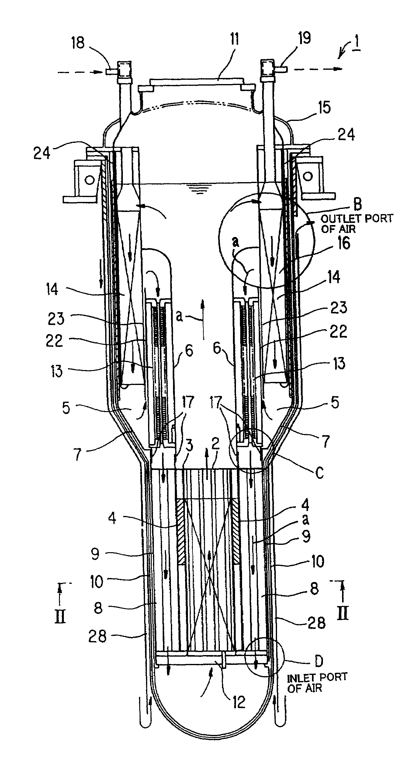
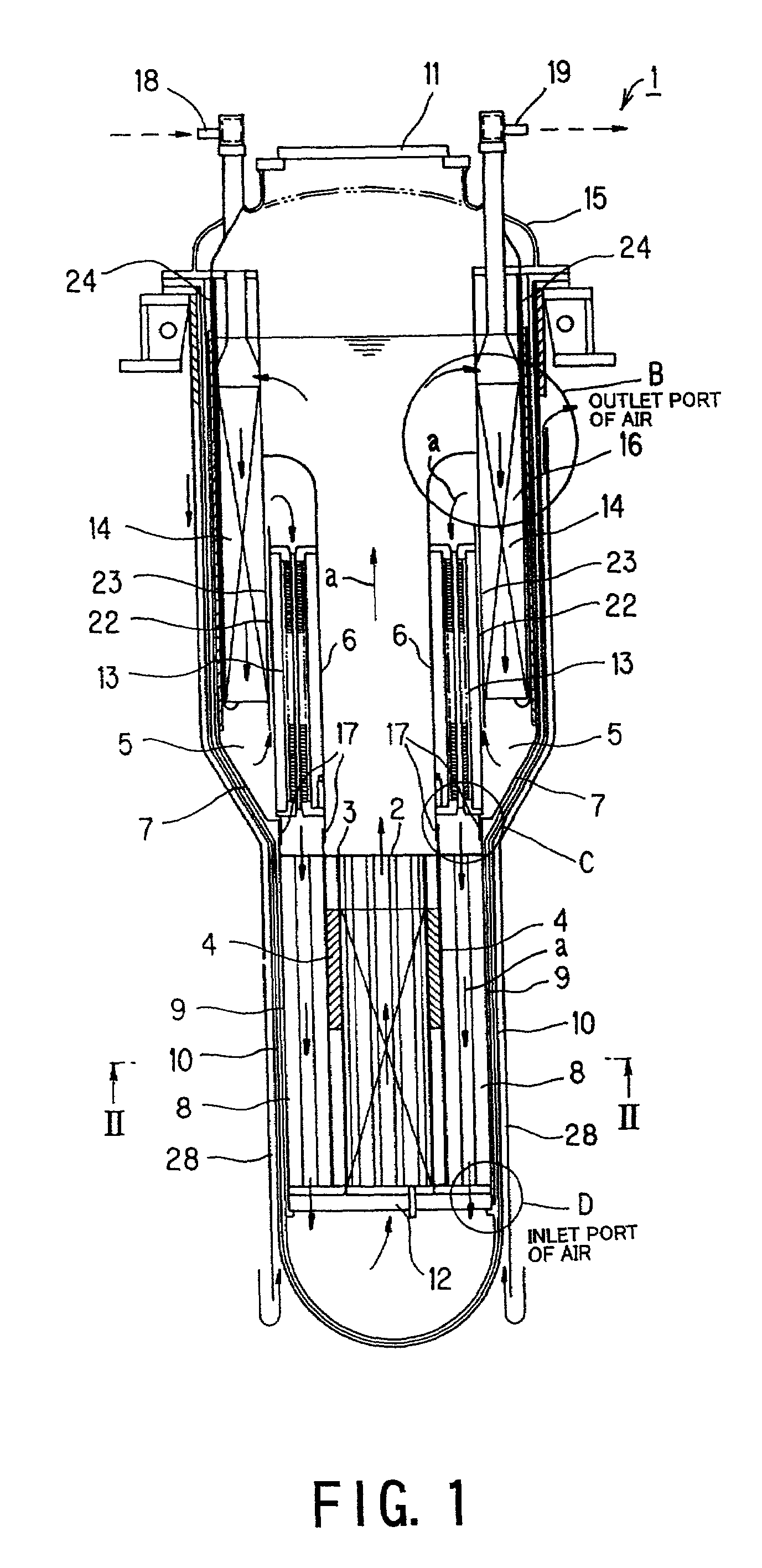
[0020]Accordingly, it is an object of the present invention to provide a nuclear reactor, which is capable of limiting a space for housing a liquid metal used as a coolant into an inside of a reactor vessel thereof so as to prevent scattering of the coolant to the outside thereof, whereby it is possible to make simple the whole structure of the nuclear reactor with a cooling facility, and to make compact the whole structure thereof, and to provide a nuclear power plant comprising the nuclear reactor.
[0025]According to the present invention, it is possible to reduce a heat value dispersed to the outside, thereby improving a heat efficiency thereof, and to make the reactor vessel compact into a small size as a whole, thereby securely preventing a leakage of the liquid metal.
[0026]Furthermore, according to the present invention, because the whole of the reactor vessel is kept at a suitable temperature, and is protected from a rapid heat transit, it is possible to secure a structural safety of the reactor, and to make an operation of the reactor for a long period. In addition, after a shutdown of the reactor, because a natural circulating force generated by heating of the core and radiation from the reactor vessel is effectively used, it is possible to stably carry out a decay heat removal operation of the reactor.
[0027]Still furthermore, in particular, the shape of the reactor is miniaturized in its longitudinal direction, and therefore, it is possible to prevent a contact of the liquid metal with the water so as to make an operation of the reactor for a long period.

Problems solved by technology

For this reason, the reactor vessel and a facility using the liquid metal arranged around the reactor vessel have complicated structures, so that there is the possibility that an auxiliary facility is required in preparation for a leakage of the activated liquid metal, fire caused thereby or the like.
For this reason, in cases where a water leakage occurs in a heating tube of the steam generator, it is difficult to avoid an occurrence of an accident caused by the reaction between the sodium and the leaked water.
In addition, a facility for housing the reaction product must be required so that there is the possibility that the reactor system, as a whole, is made into a large size thereof, and that the cost of manufacturing the reactor system is made to be increased.
The reactor with a large size in its axial direction has a structure which is easily oscillated, thereby making it unstable.
Furthermore, in cases where the fuel length of the fuel assembly is made long, the reactor vessel of the reactor becomes long as a whole; as a result, there is the possibility of deteriorating the economics of the reactor.
Furthermore, there are problems of causing a change of reactivity by deformation of the core in the lifetime thereof the core, an increase of pullout force of the fuel assembly.

Method used


Image

  • Reactivity control rod for core
  • Reactivity control rod for core
  • Reactivity control rod for core

Examples


seventh embodiment

[0187]Next, a fast reactor according to a seventh embodiment of the present invention will be described below.

[0188]According to this seventh embodiment, the reactivity control assembly has the structure in that the distribution of the neutron moderator in the diametrical direction of the cladding tube 121 is gradually dense toward an inside of the cladding tube 121.

[0189]The fast reactor of the seventh embodiment has almost the same effects as the fifth embodiment. Besides, according to the fast reactor of this seventh embodiment, it is possible to prevent a reduction of the initial neutron absorption effect, and to provide a linear reduction of the reactivity. Therefore, according to this seventh embodiment, the reactivity is linear, and the excess reactivity change by the burn-up is linear in appearance. Therefore, it is possible to linearly carry out the burn-up control by the operation of the neutron reflector 4, and thus, to carry out the operation of the neutron reflector 4 a...

eighth embodiment

[0190]Next, a fast reactor according to an eighth embodiment of the present invention will be described below.

[0191]According to this eighth embodiment, the mixture 122 in the cladding tube 121 of the reactivity control assembly 119 is formed so that the neutron moderator and the neutron absorber are mixed to be filed in the cladding tube 121, and, in this embodiment, as the neutron moderator, graphite is used. The eighth embodiment has almost the same effects as the fifth embodiment. Besides, because of using the graphite as the neutron moderator, it is possible to improve the safety of the fast reactor under the condition of high temperature, to increase the flexibility of designing the fast reactor and to correspond to the fast reactor wherein a coolant outlet temperature thereof is made high.

ninth embodiment

[0192]Next, a fast reactor according to a ninth embodiment of the present invention will be described below.

[0193]In this ninth embodiment, as shown in FIG. 20 in the fifth embodiment, the neutron absorber rod 123 is produced by mounting, as the mixture 122, the neutron moderator and the neutron absorber into the cladding tube 121 by a vibration compaction process.

[0194]More specifically, in the case of mixing zirconium hydride and gadolinium as the mixture 122 of the neutron moderator and the neutron absorber, both zirconium hydride and gadolinium are weighted by a predetermined amount, and thereafter, are molded like granules. These granules are gradually put from a top opening portion of the cladding tube 121 whose bottom end is sealed, to be filled therein, while vibration is applied to the cladding tube 121 by a vibrator. After vibration filling, an upper plug is attached onto the top opening portion of the cladding tube 121 to be sealed thereto, and thus, the neutron absorber ...


PUM


Abstract

A reactivity control rod adapted to be used in a reactor core of a fast reactor and disposed at a substantially central portion of the reactor core for controlling a reactivity therein. The reactivity control rod includes a wrapper tube surrounded by a plurality of fuel rods in a reactor core, and a plurality of neutron absorber rods arranged in the wrapper tube. At least one of the plurality of neutron absorber rods includes a cladding tube and a mixture filled in the cladding tube. The mixture is composed of a neutron absorber that absorbs a neutron and a neutron moderator that moderates the neutron.

Description

BACKGROUND OF THE INVENTION[0001]1. Field of the Invention[0002]The present invention relates to a reactivity control rod for a core, a core of a nuclear, a nuclear reactor and a nuclear power plant.[0003]More particularly, the present invention relates to a reactivity control rod for a core, which can elongate the lifetime of the core, a core of a nuclear reactor composed of the reactivity control rod, which can have a long lifetime, a nuclear reactor which is cooled by a liquid metal and is able to reduce scattering of the liquid metal so as to be made into a small size thereof and a nuclear power plant which comprises the nuclear reactor.[0004]2. Description of the Related Art[0005]A conventional liquid metal cooled nuclear reactor with a small size, that is, a fast reactor is disclosed in U.S. Pat. No. 5,420,897.[0006]Moreover, a conventional fast reactor has a structure for moving a neutron reflector in a vertical direction so as to adjust (control) a leakage of neutron from th...

Claims


Application Information

Patent Timeline
Patent Type & Authority Patents(United States)
IPC IPC(8): G21C7/06G21C1/00G21C1/32G21C5/00G21C7/103
CPCG21C1/02G21C1/32G21C1/322G21C3/02G21C5/00G21C7/04G21C7/103G21Y2002/201G21Y2002/207G21Y2002/301G21Y2002/50G21Y2004/30Y02E30/34Y02E30/39Y02E30/35Y02E30/30
Inventor NISHIGUCHI, YOHEIYOKOYAMA, TSUGIOMATSUMIYA, HISATOTSUBOI, YASUSHI
Owner KK TOSHIBA
Why Eureka
Try Eureka