Eureka AIR delivers breakthrough ideas for toughest innovation challenges, trusted by R&D personnel around the world.

Improved spiral wing water meter

An improved wing water meter technology, which is applied in the direction of volume/mass flow generated by detecting the dynamic effect of fluid flow and mechanical effect, can solve the problems of inaccurate measurement, unbalanced force on blades, and reduced accuracy, etc., to achieve The effect of improving measurement accuracy, improving measurement accuracy and increasing stability

Inactive Publication Date: 2011-08-03
沈兴家
View PDF4 Cites 4 Cited by
  • Summary
  • Abstract
  • Description
  • Claims
  • Application Information

AI Technical Summary

Problems solved by technology

During the use of this spiral wing water meter, the following problems were found: (1) When the water flow passed through the deflector 03, due to the need to adjust the flow rate, one side of the impeller 04 blade was impacted by the water flow, and the blades were unbalanced in force The swing back and forth affects the stability of the water flow, and the long-term unbalanced water flow impact will cause the impeller shaft to wear and cause the water flow to be unstable and reduce the accuracy; (2) When the water flow passes through the deflector 03, due to the difference in structural design , causing part of the water flow to overflow out of the deflector 03, resulting in inaccurate measurement; (3) when the water flow flows out from the helical blade through the impeller bracket 05, a spiral parabolic fluid is generated to cause turbulent flow in the housing; (4) the impeller drive Shaft 07 adopts worm gear transmission mode, which needs to be designed with an eccentric shaft, causing the circulating water flow to collide with the transmission shaft, resulting in uneven water flow and affecting the accuracy of measurement

Method used


Image

  • Improved spiral wing water meter
  • Improved spiral wing water meter
  • Improved spiral wing water meter

Examples


Embodiment Construction

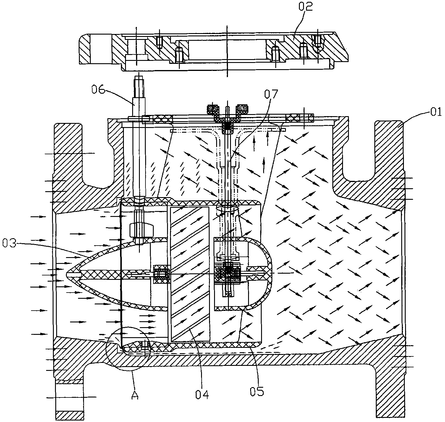
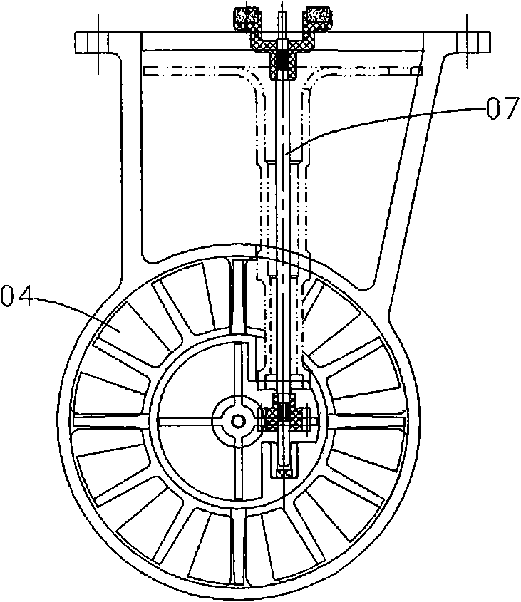
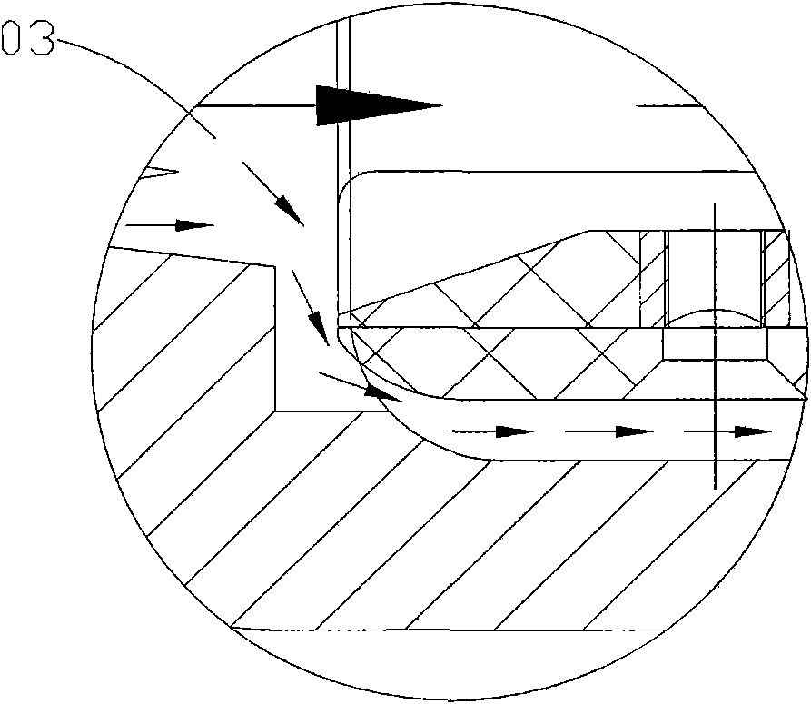
[0025] See Figure 4 and Figure 5 As shown: the improved spiral wing water meter of the present invention includes a housing 10 and a flange cover 20, wherein, the housing 10 is provided with a deflector 11, an impeller 12, and an impeller bracket 13, and the housing 10 is also provided with two sets of Adjustable rectifiers 30 , one set of adjustable rectifiers 30 is located between the deflector 11 and the impeller 12 , and the other set of adjustable rectifiers 30 is located at the rear end of the impeller support 13 . See Figure 5 and Figure 6 As shown: the adjustable rectifier 30 includes a rectifier main body 31, a plurality of movable blades 32, an adjustment connecting rod group 33, a transmission gear (including a bevel gear and a disc gear) 34, and a fixed blade 35, wherein the movable blade 32 and the fixed blade The vanes 35 are staggeredly distributed on the inner wall of the main body 31 of the rectifier, and the movable vanes 32 driven by the transmission ...


PUM


Abstract

The invention discloses an improved spiral wing water meter which comprises a shell and a flange cover, wherein the shell is internally provided with a fluid director, an impeller, an impeller bracket and two groups of adjustable rectifiers; and one group of adjustable rectifiers is located between the fluid director and the impeller, and the other group of adjustable rectifiers is located at the rear end of the impeller bracket. In the invention, because the two groups of adjustable rectifiers are additionally arranged in the shell, blades of the impeller are subject to force equilibrium, the water flow more stably flows in the shell, and the metering precision degree of the water meter is improved. In addition, because a water-blocking rubber gasket is installed at the periphery of the fluid director, exhaust holes are arranged on the blades of the impeller, a V-shaped water-blocking annular plate is arranged on the skirt rim of the impeller bracket and a deceleration impeller is arranged at the rear end of the impeller, the water flow stability is further increased and the metering precision of the gas meter is improved.

Description

Technical field: [0001] The invention relates to the technical field of measuring instruments, in particular to a spiral wing water meter used for measuring water consumption. Background technique: [0002] See Figure 1 to Figure 3 As shown: the existing spiral wing water meter has a housing 01 and a flange cover 02, wherein the housing 01 is provided with a deflector 03, an impeller 04, and an impeller bracket 05. In addition, the inner dome of the deflector 03 is provided with a There are adjustment pieces and connecting rod group 06 for adjusting the size of the flow. During the use of this spiral wing water meter, the following problems were found: (1) When the water flow passed through the deflector 03, due to the need to adjust the flow rate, one side of the impeller 04 blade was impacted by the water flow, and the blades were unbalanced in force The swing back and forth affects the stability of the water flow, and the long-term unbalanced water flow impact will caus...

Claims


Application Information

Patent Timeline
IPC IPC(8): G01F1/28
Inventor 沈兴家
Owner 沈兴家
Why Eureka
Eureka Blog
Learn More