
Lining plate device for impact plate of impact crusher

An impact crusher and impact plate technology, applied in grain processing and other directions, can solve the problems of insufficient connection strength between the lining plate and the impact plate, the impact plate liner falling off, and the damage of connecting bolts, etc., so as to reduce maintenance time and prolong use. The effect of life, easy installation and maintenance

Inactive Publication Date: 2011-08-10
NANJING KISEN INT ENG
View PDF3 Cites 4 Cited by
  • Summary
  • Abstract
  • Description
  • Claims
  • Application Information

AI Technical Summary

Problems solved by technology

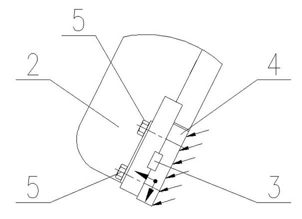
However, during the working process of the impact crusher, the impact plate is subjected to a huge impact from the material, which causes the connecting bolts to bear huge shear stress, resulting in serious damage to the connecting bolts, and often occurs that the connecting bolts are cut short and the liner of the impact plate falls. In this situation, the main reason for this situation is that the connection strength between the liner and the counterattack plate body is not enough, and the lower part of the counterattack plate is subjected to the oblique impact force of the material, so the liner bolts are simultaneously affected by two components of longitudinal and transverse forces (as shown in Figure 3. shown), the failure mode of the connecting bolts of the lining plate is shear fracture, which leads to the falling of the lining plate

Method used


Image

  • Lining plate device for impact plate of impact crusher
  • Lining plate device for impact plate of impact crusher
  • Lining plate device for impact plate of impact crusher

Examples


Embodiment Construction

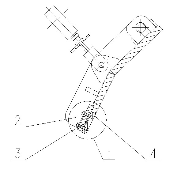
[0012] Refer below figure 1 , 2 , 3, 4 further explain the patent.

[0013] Such as figure 1 , 2 As shown, the liner device of the impact plate of the impact crusher includes the impact plate body 2 and the liner plate 4, and the liner plate is fastened on the impact plate body by connecting bolts 5. A horizontal pin key mechanism is arranged between the contact surface of the liner plate and the impact plate body. The pin key mechanism is to open a transverse square groove at the corresponding position on the contact surface of the impact plate body and the lining plate, and key the square key pin 3 into the square hole formed by the fastening of the two square grooves.

[0014] Such as Figure 4 As shown, the pin key mechanism can also be such that a transverse square groove is opened on the contact surface of the counterattack plate body and the lining plate, corresponding to the position, and a transverse square convex groove is arranged on the contact surface of the ...


PUM


Abstract

The invention discloses a lining plate device for an impact plate of an impact crusher, which comprises an impact plate body and a lining plate, wherein the lining plate is fastened on the impact plate body through a connecting bolt; the contact surfaces of the impact plate body and the lining plate are respectively provided with a transverse square groove at corresponding positions; a square key pin is keyed in a square hole formed by closing the two square grooves; or, the surface of the impact plate body in contact with the lining plate is provided with a transverse square groove, the surface of the lining plate in contact with the impact plate body is provided with a transverse square convex key corresponding to the transverse square groove, and the square convex key and the square groove are closed together. The lining plate device disclosed by the invention can transfer the transverse impact force applied to the lining plate to the impact plate body so that the shear force and the transverse impact force borne by the bolt used for connecting the lining plate with the impact plate body are greatly reduced, and the accident of falloff of the lining plate, caused by cracking and loosening of the bolt, is prevented effectively. Meanwhile, the used impact plate lining plate with a thrust structure is convenient to install and maintain, the lining plate is positioned safely and reliably, and the service life of the impact plate is prolonged effectively.

Description

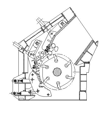
technical field [0001] The invention relates to an impact plate of an impact crusher, in particular to a liner device for the impact plate of an impact crusher. Background technique [0002] As we all know, the impact crusher uses the impact force generated by the high-speed rotation of the rotor to crush the material. The material is crushed after being hit by the hammer on the rotor. At the same time, it also has a certain kinetic energy. The high-speed material hits the impact plate for further crushing. Then the falling material is hit by the hammer head again. After such repeated crushing, when the particle size of the material is smaller than the gap between the lower part of the impact plate and the outer circle of the rotor, it will be discharged out of the crushing chamber. The impact plate is a key part of the crusher, and its design will directly affect the performance of the whole machine. [0003] The impact crusher adopts the principle of impact to crush mater...

Claims


Application Information

Patent Timeline
IPC IPC(8): B02C13/282
Inventor 邱士泉李安平徐靖周明亮季小强
Owner NANJING KISEN INT ENG
Learn More