
LED bulb

A technology of LED light bulbs and LED circuit boards, which is applied to the cooling/heating devices of lighting devices, lighting and heating equipment, semiconductor devices of light-emitting elements, etc., and can solve the problems of shortened service life of HPLEDs, no waterproof, and ineffective sealing of copper heads and other issues to achieve the effect of increasing the surface area

Inactive Publication Date: 2011-08-10
吴嘉烨
View PDF3 Cites 0 Cited by
  • Summary
  • Abstract
  • Description
  • Claims
  • Application Information

AI Technical Summary

Problems solved by technology

However, when the above-mentioned HP LED light bulb is in operation, because the Hi-Power LED will generate a lot of heat, the normal operation of the HP LED can only be maintained by dissipating the heat generated by the HP LED immediately through the aluminum alloy heat sink at the bottom of the aluminum substrate. , otherwise it will shorten the service life of the HP LED, or even burn out, so the existing HPLED bulbs generally install and fix the HP LED on the aluminum substrate, and set a finned aluminum alloy cooling device
However, the weight of the aluminum base plate and the fin aluminum alloy heat sink is relatively large, and it occupies a certain volume of the HP LED bulb, which makes the existing HP LED bulb heavy in weight, large in size and high in production cost.
In addition, the finned aluminum alloy cooling device cannot be effectively sealed with the copper head when used outdoors, and has no waterproof function

Method used


Image

  • LED bulb
  • LED bulb
  • LED bulb

Examples


Embodiment Construction

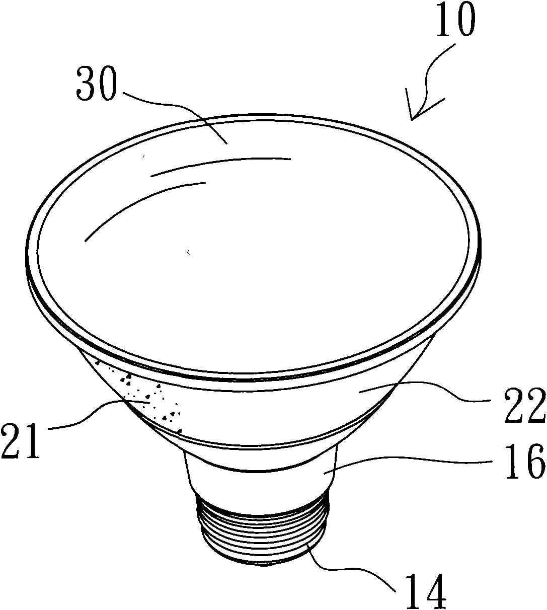
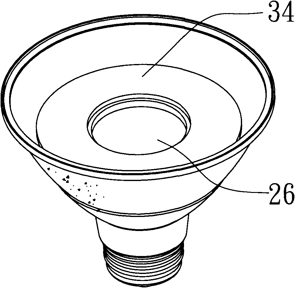
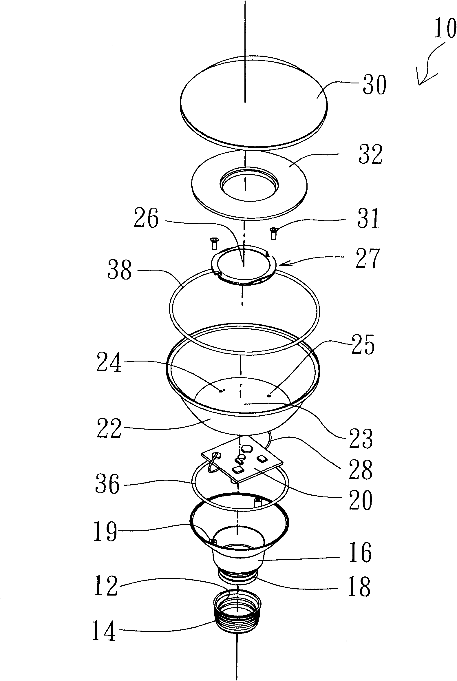
[0030] Please also refer to figure 1 , figure 2 , image 3 , Figure 4 , Figure 5 , each of which is a perspective view of the LED light bulb of the present invention, a perspective view after removing the convex lens, an exploded view of components viewed from a top view, an exploded view of components viewed from a bottom view, and a cross-sectional view.

[0031] As shown in the figure, the LED light bulb 10 of the present invention includes a lamp cap 14 with a first thread 12 formed on the inner periphery and made of copper; an insulating tube 16 with a second thread corresponding to the first thread 12 formed around its bottom end 18, to screw-lock the insulating tube 16 on the lamp cap 14, two locking holes 19 are formed on the top of the insulating tube 16; a driver circuit board assembly 20 installed in the insulating tube 16 and electrically connected to the lamp cap 14 at one end; The heat dissipation cup 22 arranged on the top of the insulating tube 16, the i...


PUM


Abstract

The invention provides an LED bulb which comprises a lamp holder, an insulating pipe, a heat radiating cup, an LED circuit board and a lamp shade, wherein the bottom end of the insulating pipe is screwed and locked on the lamp holder and the insulating pipe is internally provided with a driver circuit board assembly with one end being eclectically connected with the lamp holder; the heat radiating cup is arranged above the insulating pipe, a concave-convex pattern structure is formed on the inner surface and the outer surface of the heat radiating cup, the bottom end of the heat radiating cup is provided with two lead through holes; at least one high-power LED is arranged on the LED circuit board which is arranged on the inner bottom surface of the heat radiating cup, the LED circuit board is electrically connected with the other end of the circuit board assembly after penetrating through the lead through holes; and the lamp shaft is arranged on the top end of the heat radiating cup in a covering manner. According to the invention, heat generated by the LED is rapidly conducted and radiated by using the concave-convex pattern structure on the heat radiating cup.

Description

technical field [0001] The invention relates to a lighting fixture, in particular to an LED light bulb. Background technique [0002] In recent years, LEDs (light emitting diodes, light emitting diodes) have been widely used as light sources in daily life because of their long service life, low energy consumption, and remarkable energy saving. For example, LED light bulbs that can be directly installed in ordinary light bulb sockets have been developed to replace existing light bulbs, such as tungsten filament light bulbs. [0003] Currently, commercially available Hi-Power LED (hereinafter referred to as HP LED) light bulbs include a copper head, a lampshade, an aluminum substrate, and HP LEDs installed and fixed on the aluminum substrate. An aluminum alloy heat sink is fixed at the bottom of the aluminum substrate. The copper head is fixed on the bottom of the aluminum alloy heat sink. The copper headers are electrically connected to the HP LEDs. The lampshade is fixed...

Claims


Application Information

Patent Timeline
Patent Type & Authority Applications(China)
IPC IPC(8): F21S2/00F21V23/00F21V29/00F21V17/10F21V31/00F21V5/04F21Y101/02F21K9/235F21K9/238F21V29/70F21Y115/10
Inventor 吴嘉烨
Owner 吴嘉烨
Learn More