
Electronic component

A technology of electronic components and circuit components, applied in the field of laminated electronic components, can solve the problem of low adhesion and achieve the effect of suppressing peeling

Active Publication Date: 2011-08-10
MURATA MFG CO LTD
View PDF6 Cites 7 Cited by
  • Summary
  • Abstract
  • Description
  • Claims
  • Application Information

AI Technical Summary

Problems solved by technology

Therefore, in the laminated coil 500 , since the adhesiveness between the laminated body 512 and the insulating resin 518 is low, there is a possibility that the insulating resin 518 is peeled off from the laminated body 512 .

Method used


Image

  • Electronic component
  • Electronic component
  • Electronic component

Examples


Embodiment Construction

[0018] Next, an electronic component according to an embodiment of the present invention will be described.

[0019] (Structure of Electronic Components)

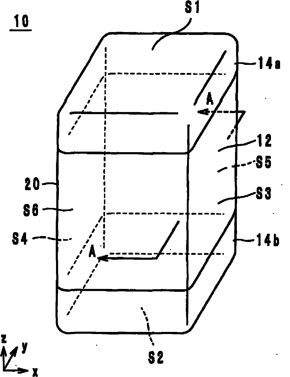
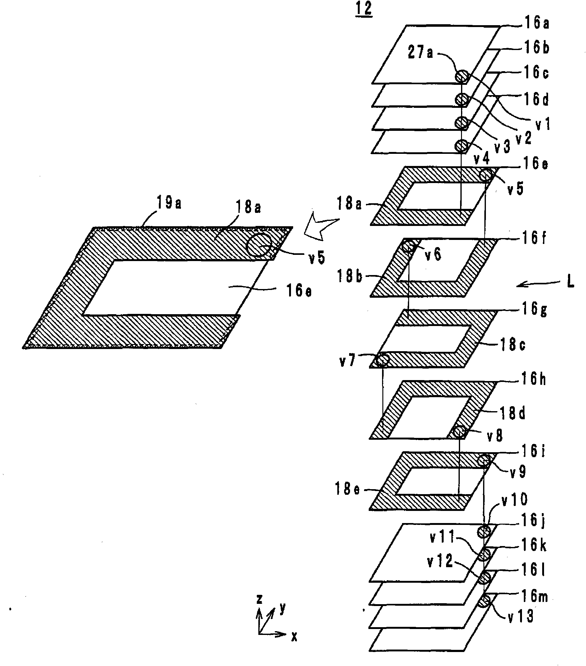
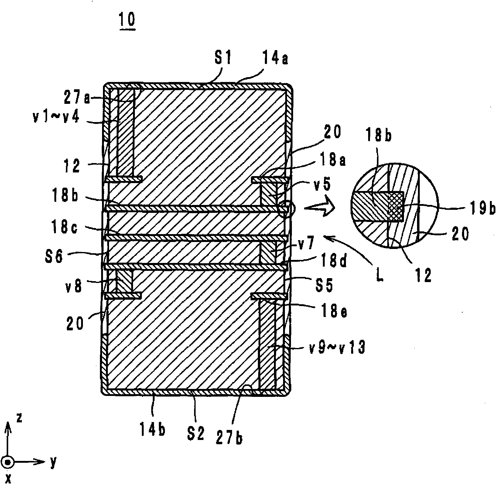
[0020] The structure of the electronic component which concerns on one Embodiment of this invention is demonstrated. figure 1 It is an external perspective view of the electronic component 10 which concerns on embodiment of this invention. figure 2 It is an exploded perspective view of the laminated body 12 of the electronic component 10 which concerns on one embodiment. image 3 yes figure 1 A-A cross-sectional structural diagram of the electronic component 10 of FIG.

[0021] Hereinafter, the stacking direction of the electronic component 10 is defined as the z-axis direction, and the direction along two sides of the surface (hereinafter referred to as upper surface S1 ) on the positive side of the z-axis direction of the electronic component 10 is defined as the x-axis. direction and the y-axis direction. The x-a...


PUM


Abstract

An electronic component is provided that allow an increase in a size of a circuit element included therein and suppression of a short-circuit-preventing insulator film from easily peeling off from a laminated body. The laminated body 12 includes a plurality of insulator layers laminated on one another. The laminated body has an upper face S1 and a lower face S2 opposing each other in a z-axis direction and lateral faces connecting the upper face S1 to the lower face S2. The insulator film 20 is provided on the lateral faces S3-S6. A circuit element such as a coil L is included in the laminated body 12 and has a part 19 protruding from the lateral faces of the laminated body 12 toward the insulator film 20.

Description

technical field [0001] The present invention relates to electronic components, and more particularly to electronic components including a laminated body incorporating circuit elements. Background technique [0002] As a conventional electronic component, for example, a laminated coil described in Patent Document 1 is known. Next, the laminated coil described in Patent Document 1 will be described. Figure 5 It is a cross-sectional structure diagram of the laminated coil 500 described in patent document 1. [0003] laminated coil 500 such as Figure 5 As shown, a laminated body 512, external electrodes 514a and 514b, an insulating resin 518, and a coil L are provided. The laminated body 512 has a plurality of laminated insulating films and has a rectangular parallelepiped shape. The coil L is a spiral coil that is built in the laminated body 512 and is configured by connecting a plurality of coil conductor patterns 516 . coil conductor pattern 516 as Figure 5 As shown, it...

Claims


Application Information

Patent Timeline
IPC IPC(8): H01F17/00H01F37/00
CPCH01F17/0033H01F17/0013Y10T29/4902Y10T29/49155
Inventor 岩崎惠介
Owner MURATA MFG CO LTD
Features
  • Generate Ideas
  • Intellectual Property
  • Life Sciences
  • Materials
  • Tech Scout
  • Unparalleled Data Quality
  • Higher Quality Content
  • 60% Fewer Hallucinations
Learn More