Centrifugal compressor and turbocharger provided with said centrifugal compressor

A technology of centrifugal compressors and impellers, which is applied in the field of centrifugal compressors and turbochargers, which can solve the problems of not being able to expand the working area on the small flow side and reduce efficiency, and achieve the effect of suppressing peeling and expanding the working area

Active Publication Date: 2019-12-17
MITSUBISHI HEAVY IND ENGINE & TURBOCHARGER LTD
8 Cites 0 Cited by

AI-Extracted Technical Summary

Problems solved by technology

However, the structure of the centrifugal compressor described in Patent Document 1 is not intended to solve the problem of reduced efficiency due to the operation in ...

Method used

Although it is also possible to have an angle range of F "(θ)=0 between the rate-of-change region and the rate-of-change increase region, in the example of Fig. 3, the rate-of-change region decreases and the rate-of-change increases The area is continuous, and the inflection point position IP at which the rate of change transitions from decreasing to increasing may also lie within an angle range from 90° to 270°. According to this configuration, since it is possible to reliably suppress a decrease in the flow velocity of the compressed air on the upstream side of the first region, it is possible to more reliably form a state where peeling is less likely to occur.
[0073] In one embodiment, the vortex flow path 5 (refer to FIG. 1) is in the range of angle range θ from 60° to 270°, including F(θ) changing at a rate of change smaller than the reference rate of change Δ the first area of ​​. Here, the rate of change of F(θ) corresponds to the gradient of the tangent to F(θ). It should be noted that F(θ) can be arbitrarily changed within the range from the downstream end of the first region to the angular position θ=360°. In the first region, compared with the case where F(θ) changes at the reference rate of change Δ, the rate of expansion of the cross-sectional area of ​​the swirl flow path 5 is reduced, ...

Abstract

The invention provides a centrifugal compressor and a turbocharger provided with the centrifugal compressor. The centrifugal compressor is provided with: an impeller; and a housing in which a helicalscroll flow channel is formed on the outer circumferential side of the impeller, and the circumferential position of the scroll flow channel is expressed by an angular position relative to the windingend of the scroll flow channel. When defining F(theta) = (A/R)/r, the relationships 0.35 <= F(360-degree) <= 0.65 and 0.08 * F(360-degree) <= F(60-degree) <= 0.4 * F(360-degree) are satisfied with respect to the cross-section when the scroll flow channel is intersected by a plane that includes the axis of rotation of the impeller at the circumferential position in which the angular position is theta, where A is the cross-sectional area of the scroll flow channel, R is the distance from the axis of rotation to the scroll center in the cross-section of the scroll flow channel, and r is the radius of the impeller.

Application Domain

Technology Topic

Image

  • Centrifugal compressor and turbocharger provided with said centrifugal compressor
  • Centrifugal compressor and turbocharger provided with said centrifugal compressor
  • Centrifugal compressor and turbocharger provided with said centrifugal compressor

Examples

  • Experimental program(1)

Example Embodiment

[0053] Hereinafter, several embodiments of the present invention will be described with reference to the drawings. However, the scope of the present invention is not limited to the following embodiments. The dimensions, materials, shapes, and relative arrangements of the structural components described in the following embodiments are not intended to limit the scope of the present invention to these, but are merely illustrative examples.
[0054] Taking a centrifugal compressor of a turbocharger as an example, the centrifugal compressor of several embodiments of the present invention shown below will be described. However, the centrifugal compressor of the present invention is not limited to the centrifugal compressor of the turbocharger, and may be any centrifugal compressor that works alone. In the following description, although the fluid compressed by the compressor is air, it can be replaced with any fluid.
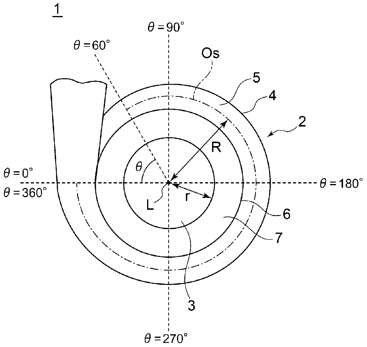
[0055] Such as figure 1 As shown, the centrifugal compressor 1 has a casing 2 and an impeller 3 rotatably provided in the casing 2 with a rotation axis L as the center. The housing 2 has: a scroll portion 4 in which a scroll-shaped scroll flow path 5 is formed on the outer peripheral side of the impeller 3, and a scroll portion 4 formed along the circumferential direction of the scroll flow path 5 on the radial inner side of the scroll flow path 5 The diffuser 6 of the diffuser flow path 7 communicating with the swirl flow path 5.
[0056] In the present invention, the angular position θ, which is the central angle centered on the rotation axis L, represents the circumferential position based on the winding end of the scroll portion 4. Therefore, the angular position θ indicating the circumferential position of the winding end is 0°. However, the position of the winding end used to represent the winding end from the winding end along the vortex flow path 5 and returning to the winding end is expressed as an angular position θ=360°. In addition, an arbitrary range in the circumferential direction can be expressed by the range of the angular position θ, and the range expressed by the range of the angular position θ is defined as the angular range.
[0057] For the cross section in the case where the vortex flow path 5 is cut by a plane including the rotation axis L at the circumferential position at the angular position θ, the cross-sectional area of ​​the vortex flow path 5 is set to A, and it is set from the rotation axis L to The vortex center O of the cross section of the vortex flow path 5 S The distance of is R, and the radius of the impeller 3 is r,
[0058] Define F(θ)=(A/R)/r.
[0059] In the centrifugal compressor 1,
[0060] The value of F(θ) at angle position θ=360°
[0061] 0.35≦F(360°)≦0.65…(1)
[0062] In addition, in the centrifugal compressor 1,
[0063] The value of F(θ) at the angle position θ=60°,
[0064] 0.08×F(360°)≦F(60°)≦0.4×F(360°)…(2)
[0065] Such as figure 2 As shown, in the angle range from 60° to 360°, the vortex flow path 5 (refer to figure 1 ) Is configured to change the value of F(θ) within the range indicated by diagonal lines.
[0066] It should be noted that the condition (1) is a range of ±30% centered on F(360°)=0.5. Such as figure 1 As shown, when the centrifugal compressor 1 works in the working area on the large flow side, the friction loss may increase at the angular position θ=360°. When the centrifugal compressor 1 works in the working area on the small flow side, the friction loss may increase. At the position θ=360°, the efficiency may decrease due to the stall. By setting F(θ) as the condition (1), it is possible to balance the above-mentioned problems that can occur in the working region on the large flow side and the working region on the small flow side.
[0067] In addition, in the working area on the small flow side, the compressed air circulating in the vortex flow path 5 does not completely correspond to the change in the flow path area (change in the flow velocity) of the vortex flow path 5 and the curvature of the vortex flow path. The change in the flow direction (change in the flow direction), and peeling occurs in the vortex flow path 5 in the angle range of 90° to 180°. On the other hand, by setting the condition (2), in the working area on the small flow side, the recirculation flow introduced from the vortex flow path 5 to the diffusion flow path 7 in the vicinity of the circumferential position at an angular position of 60° is secured Therefore, with this recirculation flow, it is difficult to generate peeling in the swirl flow path 5 in the angle range of 90° to 180°. As a result, the occurrence of peeling in the scroll flow path 5 can be suppressed, and therefore, the working area on the side of the small flow rate can be enlarged.
[0068] It should be noted that although condition (2) indicates that F (60°) is 8% to 40% of F (360°), it is not sufficient when F (60°) is less than 8% of F (360°) The recirculation flow is ensured, so the occurrence of peeling cannot be sufficiently suppressed. In addition, when F (60°) is greater than 40% of F (360°), the effect of suppressing the occurrence of peeling by the recirculation flow is maximized, and when the recirculation flow is too much, the disadvantages increase.
[0069] Next, in the following several embodiments, the manner of change of F(θ) in the range of the angle from 60° to 360° and the effect of the change in F(θ) will be described.
[0070] Such as image 3 As shown, when the change rate in the case of constant change (increase) of F(θ) in the angle range from 60° to 360°, the reference rate of change Δ is defined as
[0071] Δ=[F(360°)-F(60°)]/(360°-60°)
[0072] That is, the reference rate of change Δ is equivalent to image 3 The inclination of the line drawn by the one-dot chain line.
[0073] In one embodiment, the swirl flow path 5 (refer to figure 1 ) In the angle range θ from 60° to 270°, the first region where F(θ) changes at a rate of change smaller than the reference rate of change Δ is included. Here, the rate of change of F(θ) corresponds to the inclination of the tangent to F(θ). It should be noted that F(θ) can be changed arbitrarily from the downstream end of the first region to the angular position θ=360°. In the first region, compared with the case where F(θ) changes at the reference rate of change Δ, the expansion rate of the cross-sectional area of ​​the vortex flow path 5 is reduced. Therefore, in the first region, it is possible to suppress the vortex flow path. The flow rate of the compressed air circulating in 5 decreases. Therefore, by setting F (60°) and F (360°), the downstream side of the region where peeling is difficult to occur in the swirl flow path 5 is also formed in a state where peeling is difficult to occur, so the vortex can be further suppressed. The occurrence of peeling in the swirl flow path 5 further expands the working area on the small flow side.
[0074] It should be noted that the rate of change of F(θ) may also be smaller than the reference rate of change Δ in the entire range of the angle range from 60° to 270°, in the range of a part of the angle range from 60° to 270° Within, the rate of change of F(θ) may be smaller than the reference rate of change Δ. In the latter case, the area where the rate of change of F(θ) is smaller than the reference rate of change Δ is the first area. Therefore, the vortex flow path 5 may also at least partially include the first region in an angle range from 60° to 270°.
[0075] In this embodiment, as long as the condition that the rate of change of F(θ) is smaller than the reference rate of change Δ is satisfied, F(θ) can be changed at any rate of change. As an example, image 3 A graph showing the second-order differential F"(θ) of the angular position θ and F(θ). The first area may also include a reduced rate of change area of ​​F〃(θ)<0 within the range of the angular position θ from 60° to α (<270°), and the angular range of α to β (α 0 increases.
[0076] According to this structure, because the rate of change of F(θ) is reduced on the upstream side (range from 60° to α) of the first region, it is possible to suppress the decrease in the flow velocity of the compressed air. On the contrary, because on the downstream side of the first region (Range from α to β) The rate of change of F(θ) increases, so the decrease in the flow rate of compressed air can be alleviated. When the centrifugal compressor works in the working area on the small flow side, peeling occurs in the circumferential range of the angular position from 90° to 180°, so the flow rate of compressed air is suppressed on the upstream side of the first area When it is reduced, it is possible to more reliably form a state where peeling is difficult to occur.
[0077] Although there may be an angle range of F 〃(θ)=0 between the area where the rate of change decreases and the area where the rate of change increases, but in image 3 In the example, the decreasing area of ​​the rate of change is continuous with the increasing area of ​​the rate of change, and the inflection point position IP at which the rate of change changes from decreasing to increasing can also be within an angular range from 90° to 270°. According to this structure, it is possible to reliably suppress a decrease in the flow rate of the compressed air on the upstream side of the first region, and therefore it is possible to more reliably form a state where peeling is unlikely to occur.
[0078] In addition, in image 3 In the example, for the angular position θ at the inflection point position IP IP =α in the circumferential direction by including the rotation axis L (refer to figure 1 ) To cut the vortex flow path 5 (refer to figure 1 ), the cross-sectional area of ​​the vortex flow path 5 is A IP ,Set the rotation axis L to the vortex center O of the cross section of the vortex flow path 5 S (Reference figure 1 ) Is R IP ,
[0079] When defining F IP =(A IP /R IP )/r, it can also be
[0080] F IP
[0081] According to this structure, in the first region, in the region where the rate of change to the inflection point position IP decreases, at least F(θ) decreases compared to the case where F(θ) changes at the reference rate of change Δ, so in the first region There is a region where the flow rate of compressed air is suppressed from decreasing reliably. As a result, it is possible to more reliably suppress the occurrence of peeling in the scroll flow path 5, and it is possible to more reliably expand the working area on the side of the small flow rate.
[0082] In addition, Figure 4 Shows other embodiments. Figure 4 Relative to image 3 In the embodiment, the rate of change of F(θ) on the downstream side of the first region is specified. Therefore, the structure of the first area is image 3 The implementation is the same. In this embodiment, after the first region to the angular position θ=360°, that is, within the angular range from β to 360°, the vortex flow path 5 (refer to figure 1 ) Includes the second region where F(θ) changes at a rate of change greater than the reference rate of change Δ. In the second region, compared with the case where F(θ) changes at the reference rate of change Δ, the expansion rate of the cross-sectional area of ​​the scroll flow path 5 is increased, so the compressed air circulating in the scroll flow path 5 can be alleviated The flow rate is reduced, so sufficient static pressure recovery can be achieved.
[0083] It should be noted that in Figure 4 In the embodiment of, although the angle range from β to 360° is the second region, it is not limited to this range. At least within the angular range from 270° to 360°, it is sufficient to have a region where F(θ) is larger than the reference rate of change Δ. In this case, the area where the rate of change of F(θ) is greater than the reference rate of change Δ becomes the second area. Therefore, the vortex flow path 5 may at least partially include a second region where F(θ) changes at a rate of change greater than the reference rate of change Δ in an angular range from 270° to 360°.
[0084] In addition, Figure 5 Shows another other embodiment. Figure 5 Relative to Figure 4 In the embodiment, the change rate of F(θ) in the range from 270° to 360° is changed. In this embodiment, the second area in the range from 270° to 360° includes the difference (increase) of F(θ) at the reference rate of change Δ in the range of angle from 60° to 360° Compared with the situation, the area where the value of F(θ) increases. After the second area to the angular position θ=360°, that is, within the angular range from γ (>270°) to 360°, the vortex flow path 5 (refer to figure 1 ) Includes F(θ) at a rate of change smaller than the reference rate of change Δ, in Figure 5 In the embodiment, it is the third area where the rate of change is negative (decreased).
[0085] In the third region, compared with the case where F(θ) is changed at the reference rate of change Δ, the expansion rate of the cross-sectional area of ​​the vortex flow path 5 is reduced. Therefore, the flow velocity of the compressed air is suppressed from decreasing, and the compressed air can be reduced The inertial force of the flow toward the outlet of the scroll flow path 5 is applied to the compressed air. As a result, it is possible to suppress the flow from the vortex flow path 5 to the diffusion flow path 7 (see figure 1 ) The recirculation flow increases more than necessary, so it is possible to reduce the centrifugal compressor 1 (refer to figure 1 ) The efficiency is reduced.
[0086] in Figure 3 ~ Figure 5 In each of the embodiments, although the vortex flow path 5 includes the first region in which F(θ) changes at a rate of change smaller than the reference rate of change Δ within the angular range θ from 60° to 270°, it may be The first area is included in the angle range θ from 120° to 270°. As described above, in the working area on the side of the small flow rate, peeling occurs in the vortex flow path 5 in the angular range from 90° to 180°, but in the first half of the range where the peeling occurs, that is, the angle range is included. In the range from 90° to 120°, by setting the above conditions (1) and (2), the occurrence of peeling is suppressed, and the second half of the range where peeling occurs, that is, including the angle range is 120 In the range of ° to 180°, by making the rate of change of F(θ) smaller than the reference rate of change Δ, the occurrence of peeling can be suppressed. It should be noted that in this case, image 3 The position IP of the inflection point of the embodiment described above only needs to be within an angle range of 180° to 270°.
[0087] In this way, by setting 0.35≦F (360°)≦0.65, it is possible to balance the increase in friction loss in the working region on the large flow side and the reduction in efficiency due to stall in the working region on the small flow side. In addition, by setting 0.08×F(360°)≦F(60°)≦0.4×F(360°), in the working area on the small flow side, it is ensured that the vortex is located near the circumferential position with an angular position of 60° The recirculation flow introduced from the swirl flow path 5 to the diffusion flow path 7 makes it difficult for peeling to occur in the swirl flow path 5 in the angle range from 90° to 180° by using the recirculation flow. As a result, the occurrence of peeling in the scroll flow path 5 can be suppressed, and therefore, the working area on the side of the small flow rate can be enlarged.

PUM

no PUM

Description & Claims & Application Information

We can also present the details of the Description, Claims and Application information to help users get a comprehensive understanding of the technical details of the patent, such as background art, summary of invention, brief description of drawings, description of embodiments, and other original content. On the other hand, users can also determine the specific scope of protection of the technology through the list of claims; as well as understand the changes in the life cycle of the technology with the presentation of the patent timeline. Login to view more.

Similar technology patents

Method of manufacturing tire ply material

InactiveCN102463684AInhibition of peelingForm high qualityTyresEngineeringConductor Coil
Owner:SUMITOMO RUBBER IND LTD

Method for producing mono-cell

InactiveCN110352520AInhibition of peelingAssembling battery machinesLarge-sized flat cells/batteriesChemistryAdhesive
Owner:ENVISION AESC JAPAN LTD

Timepiece component, timepiece movement, and timepiece

ActiveCN109507860AIncreased intensityInhibition of peelingGearworksEscapementsMetal alkoxideWeight increasing
Owner:SEIKO EPSON CORP

Eccentric swing type speed reducer

Owner:SUMITOMO HEAVY IND LTD

Classification and recommendation of technical efficacy words

  • Expand the working area
  • Inhibition of peeling

Laser machining tool having expanded work space

ActiveCN102015191AReduce floor requirementsExpand the working areaLaser beam welding apparatusEngineeringTool holder
Owner:TRUMPF WERKZEUGMASCHINEN GMBH & CO KG

Inspection robot fixed-point inspection method

Owner:杭州合时机器人科技有限公司

Fluid power helical rotary actuator

ActiveUS20120263616A1Expand the working areaImprove stabilityPositive displacement pump componentsOscillating piston enginesPistonRotary actuator
Owner:ROSENBOOM MACHINE & TOOL

Earth excavation method for small foundation pit

ActiveCN105421464AIncrease the amount of excavator inputExpand the working areaExcavationsExcavatorWorking space
Owner:CHINA CONSTR EIGHT ENG DIV CORP LTD

Apparatus and method for detecting less installed screw on engine cylinder cover

ActiveCN105700037AGuaranteed brightnessExpand the working areaOptical detectionStart signalEngineering
Owner:惠州中科先进制造有限公司

Semiconductor device

InactiveCN1700467AInhibition of peelingInhibition of cracks or poor bondingSemiconductor/solid-state device detailsSolid-state devicesEngineeringSemiconductor components
Owner:KK TOSHIBA

Electronic component

ActiveCN102148088AInhibition of peelingFixed signal inductancesLower faceElectronic component
Owner:MURATA MFG CO LTD

Transmission belt

PendingCN109073041AInhibition of peelingImproves wear resistance and modulusV-beltsDriving beltsFiberTransmission belt
Owner:MITSUBOSHI BELTING LTD

Once through fan

ActiveCN103717904AEliminate stepsInhibition of peelingPump componentsRadial flow pumpsImpellerEngineering
Owner:PANASONIC CORP
Why Eureka
Try Eureka