

Timepiece component, timepiece movement, and timepiece
A technology for clocks and components, applied in clocks, gear mechanisms, escapements, etc., can solve the problems of reducing the inertial force of clock components, increasing the weight of clock components, chipping or cracking of abutting parts, etc. The effect of suppressing peeling and increasing strength
- Summary
- Abstract
- Description
- Claims
- Application Information
AI Technical Summary
Problems solved by technology
Method used
Image

Examples
no. 1 approach
[0042] Hereinafter, a first embodiment of the present invention will be described with reference to the drawings. In addition, in the first embodiment, the mechanical timepiece 1 is employed as an example of the timepiece of the present invention. In addition, as an example of the timepiece component of the present invention, the escape gear (escape gear portion) 110 will be described as an example. In each of the following figures, each layer or each member may be shown on a scale different from actual ones in order to make each layer or each member a recognizable size.
[0043] mechanical clock
[0044] First, a mechanical timepiece 1 as a timepiece according to the first embodiment will be described.
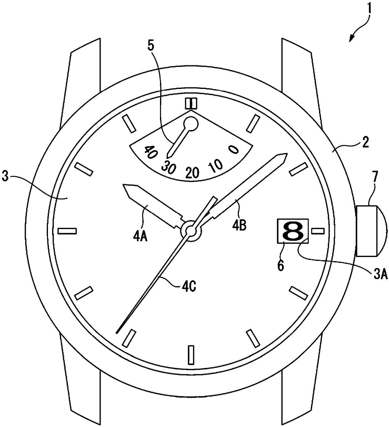
[0045] figure 1 It is a front view of the mechanical clock 1 .
[0046] The mechanical timepiece 1 includes a cylindrical exterior case 2 , and a disc-shaped dial 3 is disposed on the inner peripheral side of the exterior case 2 . Of the two openings of the exterior case...
no. 2 approach
[0187] A mechanical timepiece according to a second embodiment will be described. In addition, the same code|symbol is attached|subjected to the same structure as 1st Embodiment mentioned above, and description is abbreviate|omitted.
[0188] In the mechanical timepiece according to the second embodiment, in addition to being used as a timepiece component Figure 9 Except for the escape gear 210 shown, the rest are the same in structure as the mechanical timepiece 1 according to the first embodiment.
[0189] Figure 9 is a plan view of an escape gear 210 as a timepiece component according to the second embodiment of the present invention.
[0190] The escape gear 210 has a base made of silicon having an insertion portion 210C through which the shaft is inserted, and a film (not shown) formed on the surface of the base at least in contact with the shaft. on the abutment of the abutment.
[0191] The escape gear 210 has a flat surface with a surface 210A as one surface and ...
Embodiment approach
[0202] The present invention is not limited to the configurations of the first embodiment and the second embodiment, and various changes can be made within the scope of the gist of the present invention.
[0203] In the above-described embodiment, the escape gears 110 and 210 are illustrated as timepiece components, but the invention is not limited thereto. The timepiece components of the above-described embodiments can be applied to components constituting, for example, the barrel, the second wheel, the third wheel, the fourth wheel, the pallet fork 140 , or the balance with hairspring 27 . In addition, these timepiece components may be mounted on the movement 10 using one type alone or in combination of two or more types, or may be mounted on a timepiece.
[0204] In addition, in the above-mentioned embodiment, the case where the coating is formed on the entire surface of the substrate (the substrate without the coating formed) has been described, but the coating needs only ...
PUM
 Abstract
Description
Claims
Application Information