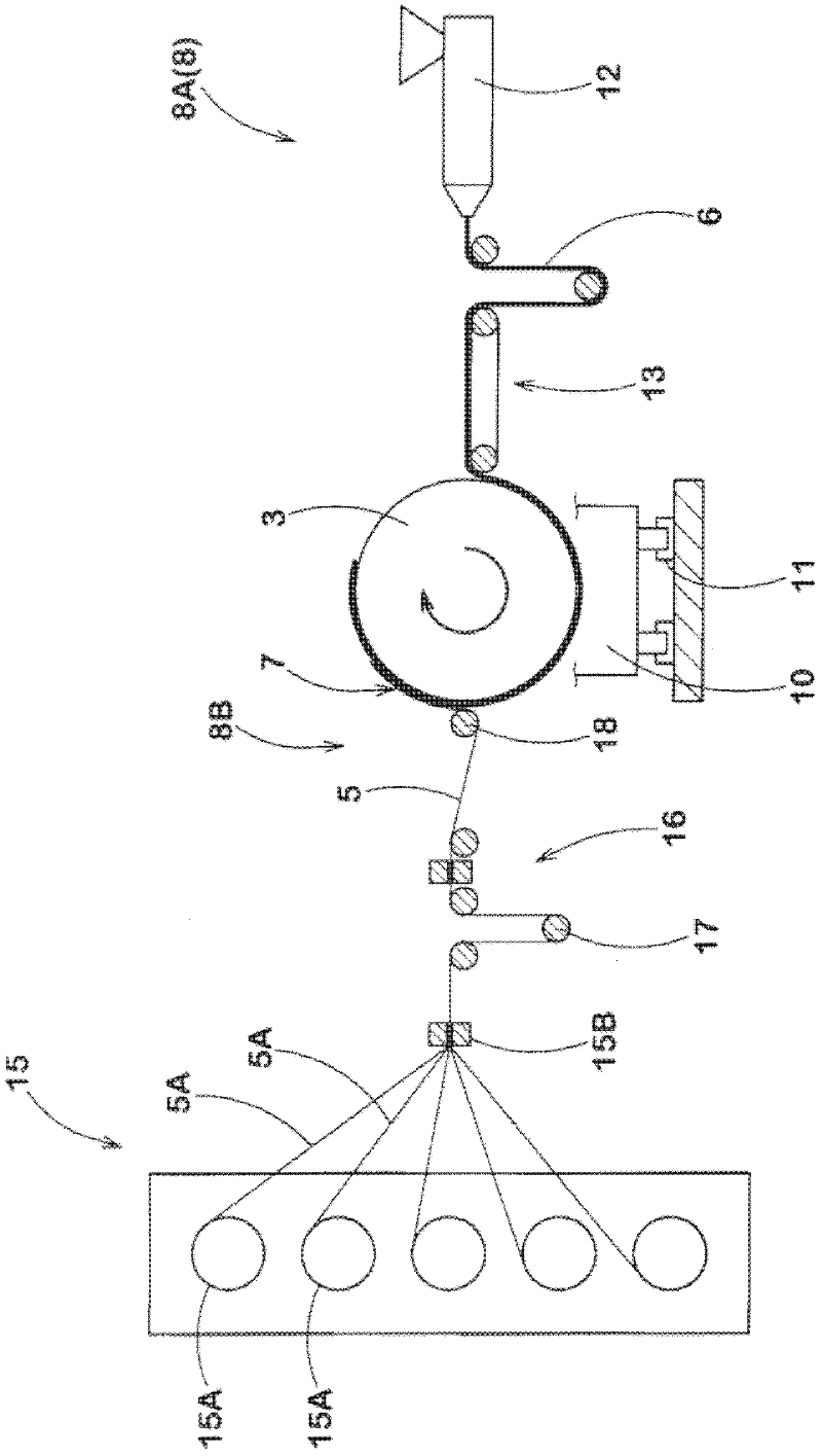
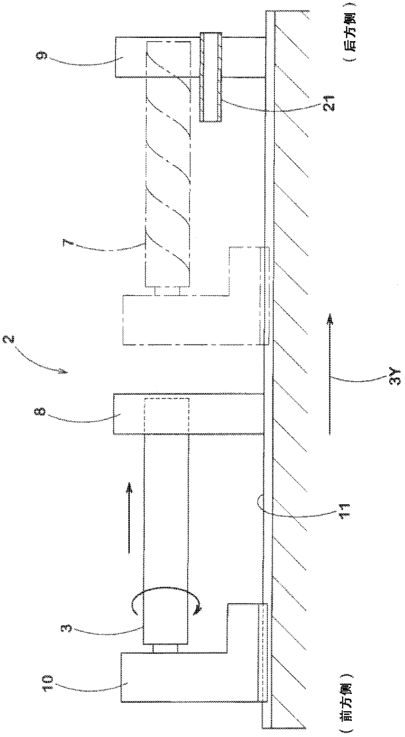
[0037] Next, embodiments of the present invention will be described in detail. figure 1 , 2 It is a front view and a side view which show an example of the manufacturing apparatus 2 which implements the manufacturing method of the tire carcass 1 of this invention.
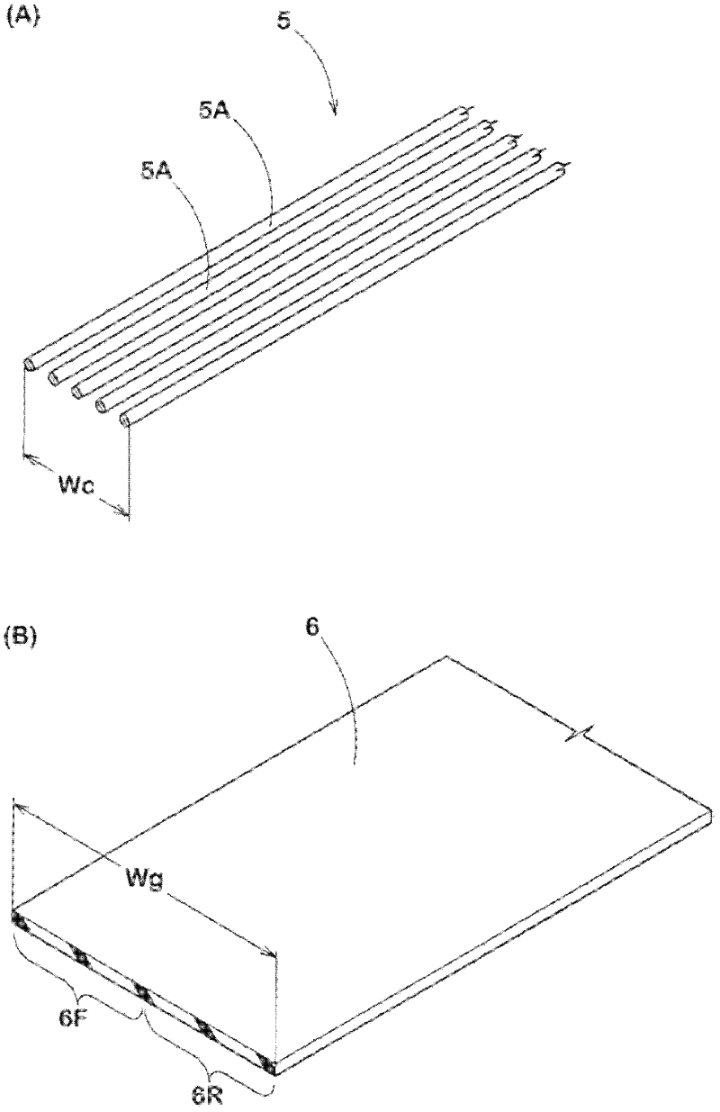
[0038] exist figure 1 , 2 Among them, the manufacturing device 2 includes: a drum 3; a winding unit 8, which continuously winds the cord array body 5 and the rubber belt 6 in a spiral shape on the drum 3 to form the cord array body 5 in the radial direction. A cylindrical cord-containing winding body 7 whose inner and outer surfaces are covered by the rubber belt 6 (in Figure 4 , 5 shown in); cutting unit 9, which cuts the cord-containing winding body 7 to form tire cord material 1 (in Image 6 shown in ).
[0039] In this embodiment, the tire cord material 1 is a cord material 1 for forming a belt cord, Figure 7 A case where the tire cords 5A are arranged at a predetermined angle θ of, for example, 10 to 40° with respect to the longitudinal direction 1Y of the carcass material 1 is exemplified.
[0040]The drum 3 is a cylindrical body rotatably supported by the drum device main body 10 , and is supported so as to be relatively movable at a certain speed toward the rear side of the drum axis 3Y with respect to the winding unit 8 . Therefore, in this embodiment, the following situation is shown: the winding unit 8 and the cutting unit 9 are installed in a fixed position, and the drum device main body 10 is supported so as to be able to move upward on the guide rail 11 laid along the drum axial direction. The rear side of the drum shaft moves at a constant speed, but it also includes, for example, installing the drum device body 10 at a fixed position, and supporting the winding unit 8 and the cutting unit 9 so as to be movable at a constant speed toward the front side of the drum shaft. .
[0041] like figure 1 As shown, the winding unit 8 has a belt winding unit 8A for winding the rubber belt 6 and a cord winding unit 8B for winding the cord array body 5 in this embodiment.
[0042] The belt winding unit 8A has, for example, a crawler-shaped conveyance unit 13 that conveys the rubber belt 6 supplied from the rubber belt supply source 12 and conveys it to the drum 3 from the tip side. Regarding the above-mentioned rubber belt supply source 12 , in this embodiment, a small rubber extruder (including a continuous mixer) is used to knead the input rubber material and extrude it into a predetermined cross-sectional shape. However, in addition to this, for example, it may be a calendering device that calenders a rubber material that has been kneaded in advance into a belt shape with a predetermined cross-sectional shape, and may also be a roller that winds a rubber belt 6 formed in advance. The shape body is kept as a rolling stand (English: Roll Stand) that can be rewound freely.
[0043] Furthermore, the cord winding unit 8B has a conveyance unit 16 that conveys the cord array 5 supplied from the cord array supply source 15 . The cord array supply source 15 has a plurality of bobbins 15A around which tire cords 5A are wound, and guides 15B for arranging the tire cords 5A rewound from the respective bobbins 15A in parallel with each other at predetermined intervals. In addition, the conveying unit 16 has: a freely movable weight roller 17 that applies a predetermined tension to the cord array 5 in order to convey the cord array 5 while suppressing disorder in arrangement; The wire array body 5 is output to the drum 3 from the tip side. In addition, a plurality of circumferential grooves (not shown) are arranged on the output roller 18 to prevent misalignment of the tire cords 5A.
[0044] In addition, the winding process K1 is performed, such as Figure 4 As shown, in the winding process K1, the rubber belt 6 and the cord arrangement are supplied from the belt winding unit 8A and the cord winding unit 8B to the drum 3 that moves at a constant speed while rotating toward the rear side of the drum shaft 3Y. body 5, so that the rubber belt 6 and the cord array body 5 are wound on the drum 3 continuously in a helical shape. At this time, the rubber belt 6 has a width Wg twice the moving distance L of the drum axis 3Y when the drum 3 makes one rotation. In addition, the width Wc of the cord array body 5 is smaller than the moving distance L described above.
[0045] Here, the moving distance L corresponds to the helical pitch P of the helical winding of the rubber belt 6 and the cord array 5 . Therefore, by making the rubber belt 6 have a width Wg twice the helical pitch P, the rubber belt 6 is made as Figure 5 As shown, it is sequentially wound in a helical manner so as to have an overlapping portion G that overlaps the drum axis of the rubber belt 6 wound in the previous round through the rear half-width portion 6R of the drum axis 3Y of the rubber belt 6 . 3Y on the front side half-width portion 6F.
[0046] And, if Figure 4 As shown, the rubber belt 6 and the cord array body 5 are spirally wound with their phases shifted in the circumferential direction. Therefore, the cord array body 5 can be wound on the front half-width portion 6F of the previously wound rubber belt 6 . Further, the rear half-width portion 6R of the rubber belt 6 wound next is disposed on the wound cord array body 5 and covered with the cord array body 5 . That is, the cord array body 5 is disposed between the rear half-width portion 6R and the front half-width portion 6F of the rubber belt 6 of the overlapping portion G, whereby the inner and outer surfaces of the cord array body 5 in the radial direction are formed. A cylindrical cord-containing winding body 7 covered by the rubber belt 6 . In addition, in figure 1 In the drawing, the rubber belt 6 and the cord array body 5 are drawn so that they are wound with a phase shift of about 180° in the circumferential direction, but it is not limited to this, and may be wound as described above. Figure 4 As shown, the phase in the circumferential direction is set to be small.
[0047] In this winding method, since the rubber belts 6 overlap each other at half-width and half-width and are sequentially joined, it is possible to firmly join between the rubber belts 6 and 6 and between the rubber belt 6 and the cord array body 5. When the cord-containing winding body 7 is cut off from the tire carcass 1 and when the cut tire carcass 1 is supplied to a green tire forming process, etc., peeling at the joint portion can be reliably suppressed.
[0048] also, Figure 4 Reference numeral 20 in the figure is a pressing roller, and by sequentially pressing the wound cord array body 5 and rubber belt 6 against the drum side, mutual bonding strength can be increased. Further, it is preferable to supply the rubber belt 6 to the drum 3 in a high-temperature state of 60° C. or higher from the viewpoint of bonding strength. Thereby, even if the thrust force generated by the pressing rod 20 is small, the cord array body 5 and the rubber belt 6 and between the rubber belts 6 and 6 can be integrated, and the dimensional accuracy does not decrease due to the thrust force. , deformation, can obtain a firm joint strength. In addition, the upper limit of the temperature of the rubber belt 6 is the temperature at the limit of the unvulcanized rubber belt 6. Although the upper limit of the temperature of the rubber belt 6 varies with the formulation of the rubber, it is preferable in the case of a belt cord. is 80°.
[0049] Next, a cutting unit 9 is provided behind the winding unit 8 in the tire axial direction, and the cutting unit 9 executes the cutting step K2 to cut the cord-containing winding body 7 on the drum 3 to form a tire cord material 1 . Specifically, as Image 6 , 7 As shown, the cutting unit 9 has a rotary cutter 9A arranged in a direction intersecting with the circumferential direction in this embodiment. As the drum 3 moves and rotates to the rear side of the drum shaft 3Y, the cutting unit 9 is arranged at an angle α with respect to the circumferential direction. The cord-containing winding body 7 is cut spirally. Thereby, the tire carcass 1 in which the tire cords 5A are arranged at a predetermined angle θ with respect to the longitudinal direction 1Y of the carcass 1 can be continuously formed. Strictly speaking, the angle θ is the difference |α-β| between the angle β (not shown in the drawing) of the cord-containing winding body 7 with respect to the circumferential direction of the tire cord 5A and the angle α, because the The ratio P/D of the helical pitch P to the diameter D of the drum 3 is very small, so β≈0, and therefore, the ply material 1 can generally be formed to be θ≈α.
[0050] In addition, the cutting position is provided with an output crawler 21 facing a direction perpendicular to the drum axis 3Y, and the carcass 1 cut by the cutting unit 9 is output to a raw tire forming process which is a subsequent process. In addition, by adjusting the formation width Wo of the cord-containing winding body 7, the cutting angle α (≈θ), and the diameter D of the drum 3, it can be formed with a width W1, a cord angle θ, and a length L1 corresponding to the size of the tire. The tire ply material 1 used for one tire.
[0051] Next, another example of the winding step K1 will be described. In this example, if Figure 8 As shown, in the winding step 1, the rubber belt 25 with cords in which the cord array body 5 and the rubber belt 6 are previously integrally bonded before being wound on the drum 3 is used. Specifically, as shown in the figure, the corded rubber belt 25 integrally bonds the cord array body 5 to the front half-width portion 6F of the rubber belt 6 .
[0052] In addition, if Figure 9 As shown, the corded rubber belt 25 is helically and continuously wound on the drum 3 at the said helical pitch P. As shown in FIG. Thus, the rear half-width portion 6R of the corded rubber belt 25 wound next is arranged on the cord array body 5 of the corded rubber belt 25 wound in the preceding round, and covers the cord array body. 5. That is, the cord array body 5 is disposed between the rear half-width portion 6R and the front half-width portion 6F of the rubber belt 6 of the overlapping portion G, whereby the inner and outer surfaces in the radial direction of the cord array body 5 are formed. A cylindrical cord-containing winding body 7 covered by the rubber belt 6 .
[0053] Preferred embodiments of the present invention have been described in detail above, however, the present invention is not limited to the illustrated embodiments, and can be implemented with various modifications.