Wireless receiving device and method for reducing received noise by utilizing diversity antenna
A technology of wireless receiving device and diversity antenna, applied in diversity/multi-antenna system, space transmit diversity, polarization/direction diversity and other directions, can solve the problem of not reducing the internal and surrounding radiation noise of the terminal, and not improving the C/N, High cost and other problems, to achieve the effect of improving receiving sensitivity, reducing radiation noise, and reducing costs
- Summary
- Abstract
- Description
- Claims
- Application Information
AI Technical Summary
Problems solved by technology
Method used
Image
Examples
Embodiment approach 1
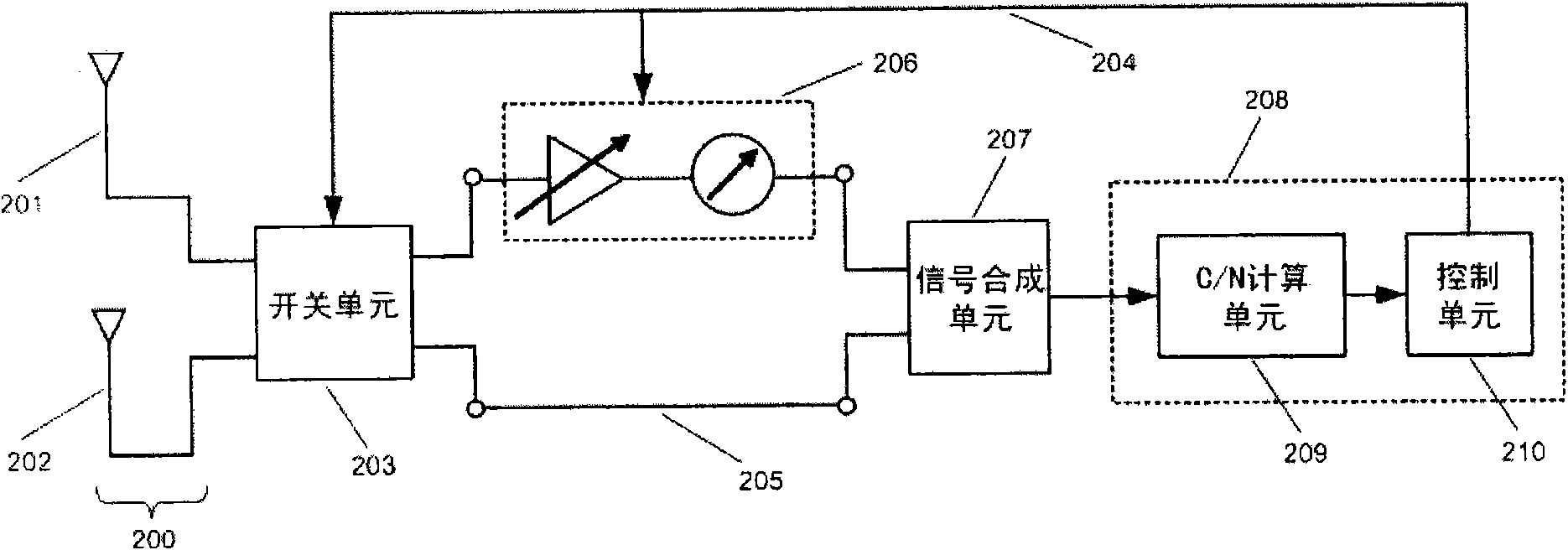
[0023] figure 2 is a block diagram of a radio receiving apparatus for reducing reception noise using diversity antennas according to the first embodiment of the present invention. Refer below figure 2 The configuration and operation of a wireless receiving apparatus for reducing reception noise using diversity antennas according to the first embodiment of the present invention will be described.
[0024] Such as figure 2 As shown, according to the first embodiment of the present invention, the wireless receiving device utilizing a diversity antenna to reduce reception noise includes a diversity antenna 200, a switch unit 203, a direct circuit 205, an amplitude and phase adjustment circuit 206, a signal synthesis unit 207, and a C / N calculation unit 209 and control unit 210. The control unit 210 is connected to the switch unit 203 and the amplitude and phase adjustment circuit 206 through the line 204 for controlling the switch unit 203 and the amplitude and phase adjustm...
Embodiment approach 2
[0038] In Embodiment 1 above, the first embodiment of the wireless receiving device of the present invention for reducing reception noise by using a diversity antenna is described by taking the example that the diversity antenna includes two antenna units.
[0039] As the size of mobile terminals becomes smaller and thinner, there is no room for two antenna units in many mobile terminals. Embodiment 2, that is, the second embodiment, describes a wireless receiving device that uses only one antenna unit to achieve diversity reception through phase processing.
[0040] Figure 5 An embodiment is shown in which a diversity antenna receiving device is implemented using one antenna unit. Such as Figure 5 As shown, the antenna unit 501 is composed of an antenna element 502 and an antenna element 503 . Each of the branches of the two antenna elements is connected with a phase shifter, the phase shifters in the two branches of the antenna element 502 are +90 degree phase shifters ...
Embodiment approach 3
[0046] In the first embodiment described above, it is necessary to evaluate the C / N of the signals received by the antenna unit 201 and the antenna unit 202 respectively through switching of the switch unit 203 first. If the switching speed is too slow, in order to prevent the switching of the switch from causing the received signal to be intermittent, once the signal with a relatively good C / N and the signal with a relatively poor one are determined, this premise will be defaulted until the C / N cannot reach the threshold. However, for places where the signal reception environment is harsh, such as large multipath interference and weak signals, if the receiving status such as the orientation of the mobile terminal is often changed, it needs to be executed multiple times. image 3 The process shown will affect the receiving effect. To solve this problem, Figure 7 A diversity antenna wireless receiving device according to a third embodiment of the present invention is shown. ...
PUM
 Abstract
Description
Claims
Application Information
 - R&D
- Intellectual Property
- Life Sciences
- Materials
- Tech Scout
- Unparalleled Data Quality
- Higher Quality Content
- 60% Fewer Hallucinations
Browse by: Latest US Patents, China's latest patents, Technical Efficacy Thesaurus, Application Domain, Technology Topic, Popular Technical Reports.
© 2025 PatSnap. All rights reserved.Legal|Privacy policy|Modern Slavery Act Transparency Statement|Sitemap|About US| Contact US: help@patsnap.com


