
Friction welded steel piston having optimized cooling channel

A cooling channel, friction welding technology, applied in the direction of piston, machine/engine, mechanical equipment, etc., can solve the problems of reduced coolant exchange, affecting piston cooling, disadvantage, etc., and achieve the effect of preventing flow influence

Inactive Publication Date: 2011-08-10
KOLBENSCHMIDT AG
View PDF10 Cites 16 Cited by
  • Summary
  • Abstract
  • Description
  • Claims
  • Application Information

AI Technical Summary

Problems solved by technology

As a result, the coolant exchange is reduced, which directly and adversely affects the cooling of the pistons

Method used


Image

  • Friction welded steel piston having optimized cooling channel
  • Friction welded steel piston having optimized cooling channel
  • Friction welded steel piston having optimized cooling channel

Examples


Embodiment Construction

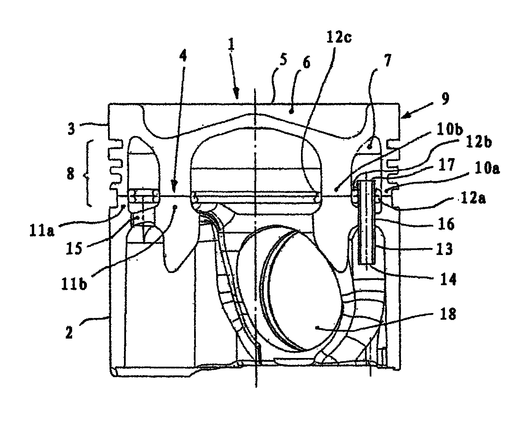
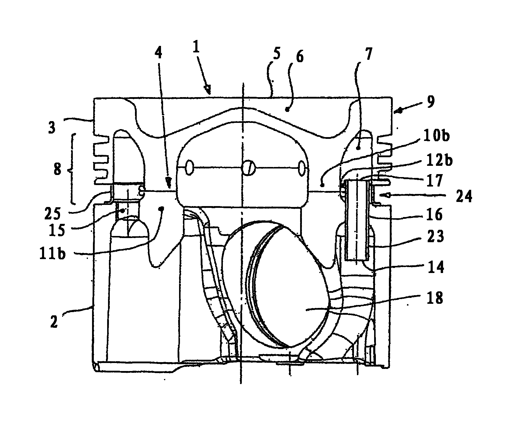
[0030] figure 1 A piston 1 is shown in half section, comprising a lower part 2 and an upper part 3 , which are joined together in the region of the contact geometry 4 by means of friction welding to form a structural unit. The upper part 3 of the piston 1 forms a combustion chamber cavity 6 in the region of the piston crown 5 . The ring-shaped cooling channel 7 integrated in the piston 1 extends from the upper part 3 into the lower part 2 and extends here at a radial distance from the piston ring region 8 , which is formed in the outer contour 9 . out. The upper part 3 comprises rotationally symmetrically extending, radially offset joint bridges 10 a , 10 b which, together with corresponding joint bridges 11 a , 11 b of the lower part 2 , form the contact geometry 4 . By means of friction welding, which is visible through the weld seam elevations 12a, 12b, 12c, the joining bridges 10a, 10b; 11a, 11b are materially connected in the region of the contact geometry 4 to create a...


PUM


Abstract

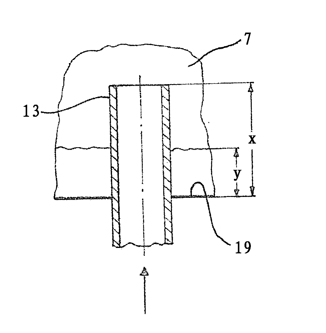
The invention relates to a piston (1) of an internal combustion engine comprising an upper part (3) made of steel and a bottom part (2) bonded by means of friction-welding in the region of a contact geometry (4) by means of joining bars (10a, 10b; 11a, 11b) to form an assembly. At least one cooling channel (7) permeated by a cooling agent is integrated in the piston (1), wherein a lubricating oil of the internal combustion engine enters an inlet opening (14) as a cooling agent by means of a free stream of an injector, flows through the cooling channel (7), and exits via an exit opening (15). In order to introduce the cooling agent into the cooling channel (7), the inlet opening (14) is associated with a flow pipe (13) mounted in the bottom part (2) and protruding out of a cooling channel floor (19), the opening (17) thereof being disposed above weld coils (12a, 12b) of the friction welder.

Description

technical field [0001] The invention relates to a steel piston of an internal combustion engine comprising an upper part and a lower part, the joining bridges of which are in the region of the contact geometry in a material-fit manner by means of friction welding (stoffschlüssig ) to form a structural unit. For cooling, at least one cooling channel, which is acted upon by coolant, is integrated in the piston. Coolant—lubricating oil of the internal combustion engine enters the inlet opening through the free jet of the injection nozzle, flows through the cooling channel and leaves it through the outlet opening. Background technique [0002] Areas of the piston of an internal combustion engine that are highly thermally loaded, for example the area of ​​the combustion chamber cavity or the first groove in the piston crown, require effective cooling. For this purpose, it is known to integrate cooling channels in the piston. A coolant, preferably lubricating oil of the interna...

Claims


Application Information

Patent Timeline
IPC IPC(8): F02F3/00F02F3/22B23P15/10
CPCF02F2003/0061B23P15/10F02F3/22F02F3/003
Inventor V·格尼斯默
Owner KOLBENSCHMIDT AG
Learn More