Apparatus for recovering vent steam and drain

A technology for recycling device and condensate water, which is applied in steam engine devices, steam generation methods using heat carrier, water heaters, etc., can solve the problems of inability to form differential pressure, damage to water supply pumps, slow thermal cycle, etc., to reduce the use of steam , the effect of improving the comprehensive heat transfer coefficient and improving the heat transfer effect

Active Publication Date: 2011-08-10
YEONGIL PUMPTECH
View PDF11 Cites 3 Cited by
  • Summary
  • Abstract
  • Description
  • Claims
  • Application Information

AI Technical Summary

Problems solved by technology

[0014] However, a steam heating device without a steam trap can transfer condensed water by gravity, but if the part of the steam that is not released is released to the atmosphere, a differential pressure cannot be formed, resulting in a slow thermal cycle.
[0015] Also, when the water supply pump for transferring the condensed water trapped in the water supply tank is activated, there is a problem of causing damage to the water supply pump due to cavitation

Method used


Image

  • Apparatus for recovering vent steam and drain
  • Apparatus for recovering vent steam and drain
  • Apparatus for recovering vent steam and drain

Examples


Embodiment Construction

[0033] The preferred embodiments according to the present invention will be described below with reference to the accompanying drawings.

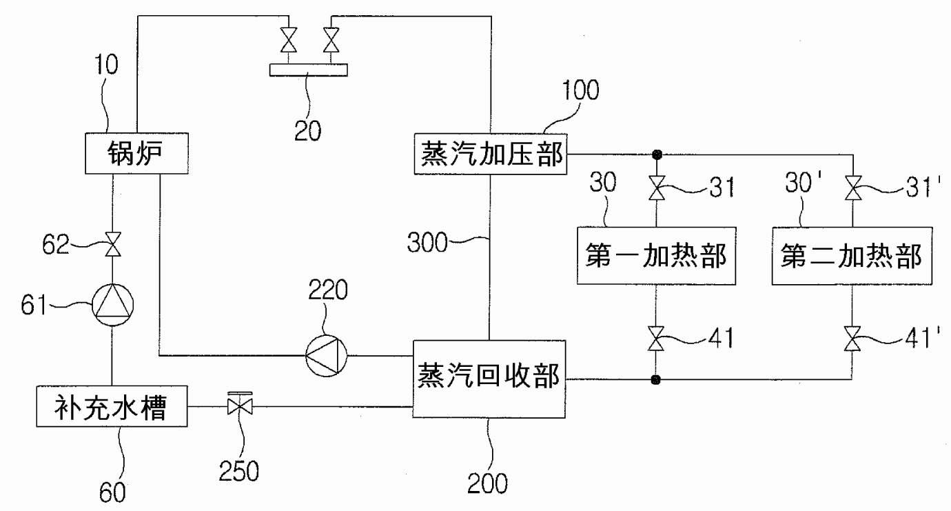
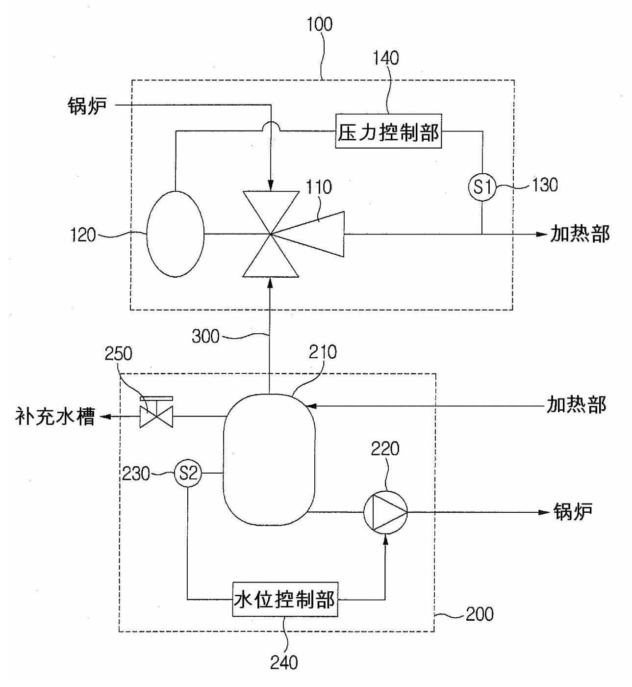
[0034] figure 2 It is a block diagram of the boiler system utilizing the re-evaporation steam and condensed water recovery device according to the present invention, image 3 is a block diagram showing the composition of the reevaporation steam and condensed water recovery device according to the present invention, and Figure 4 It is a sectional view showing the composition of the steam recompression control valve in the reevaporation steam and condensed water recovery device according to the present invention.

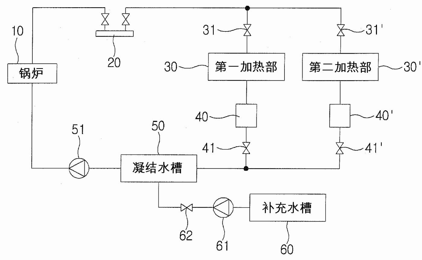
[0035] First, the same constituent elements as those in the prior art will not be repeatedly described, and the same symbols will be used for the same constituent elements as in the prior art.

[0036] Such as Figure 2 to Figure 4 As shown, the re-evaporation steam and condensed water recovery device according to the present ...


PUM


Abstract

The present invention relates to an apparatus for recovering re-evaporated steam and condensate, and in particular, to an apparatus for mixing the steam re-evaporated from condensate that is discharged from a heating unit for heating an object to be treated, with high-temperature steam supplied from a boiler, and for resupplying the mixed steam to the heating unit. To this end, the apparatus comprises: a steam recovery unit for recovering the condensate discharged from a heating unit for heating an object to be treated, and the steam re-evaporated from the condensate, and then supplying the recovered re-evaporated steam to a steam pressurizing unit and the recovered condensate to a boiler; and the steam pressurizing for mixing the re-evaporated steam supplied from the steam recovery unit, with high-temperature steam supplied from the boiler and then supplying the mixed steam to the heating unit. Therefore, with a closed circuit, the apparatus can recover the whole quantity of the re-evaporated steam and condensate for use, prevent the release of steam into the air and utilize a latent heat contained in the condensate, thereby improving the efficiency of energy consumption.

Description

technical field [0001] The present invention relates to a reevaporating steam and condensed water recovery device, and more specifically relates to a device that mixes reevaporated evaporating steam from condensed water discharged from a heating part of an object to be heated with high-temperature steam supplied from a boiler. , and then supplied to the re-evaporation steam and condensed water recovery device in the heating part. Background technique [0002] A general steam heating device supplies heating steam to a heating part formed on a heat exchanger, and is connected to a condensate recovery device for discharging condensate generated by heating. [0003] figure 1 It is a structural block diagram of a traditional steam heating device, as shown in the figure, which includes: a boiler 10 for forming high-temperature steam; heating parts 30, 30' for supplying the high-temperature steam generated from the boiler 10 to the treatment object The steam trap 40, 40' is used ...

Claims


Application Information

Patent Timeline
Patent Type & Authority Applications(China)
IPC IPC(8): F24H9/16F22B1/18F24H1/00
CPCF01K13/02F22B1/18F24H1/00F24H9/16
Inventor 崔秉国崔永限
Owner YEONGIL PUMPTECH
Why Eureka
Try Eureka