Inverter apparatus, inverter control system, motor control system, and method of controlling inverter apparatus

A control method and control system technology, applied in the field of inverter device and its control, can solve problems such as inability to build a thermal model

Active Publication Date: 2011-08-10
YASKAWA DENKI KK
View PDF8 Cites 8 Cited by
  • Summary
  • Abstract
  • Description
  • Claims
  • Application Information

AI Technical Summary

Problems solved by technology

In this structure, when a power module is installed in an unknown heat sink, there is a problem that it is impossible to construct a thermal model most suitable for the installation conditions.

Method used


Image

  • Inverter apparatus, inverter control system, motor control system, and method of controlling inverter apparatus
  • Inverter apparatus, inverter control system, motor control system, and method of controlling inverter apparatus
  • Inverter apparatus, inverter control system, motor control system, and method of controlling inverter apparatus

Examples


Embodiment 1

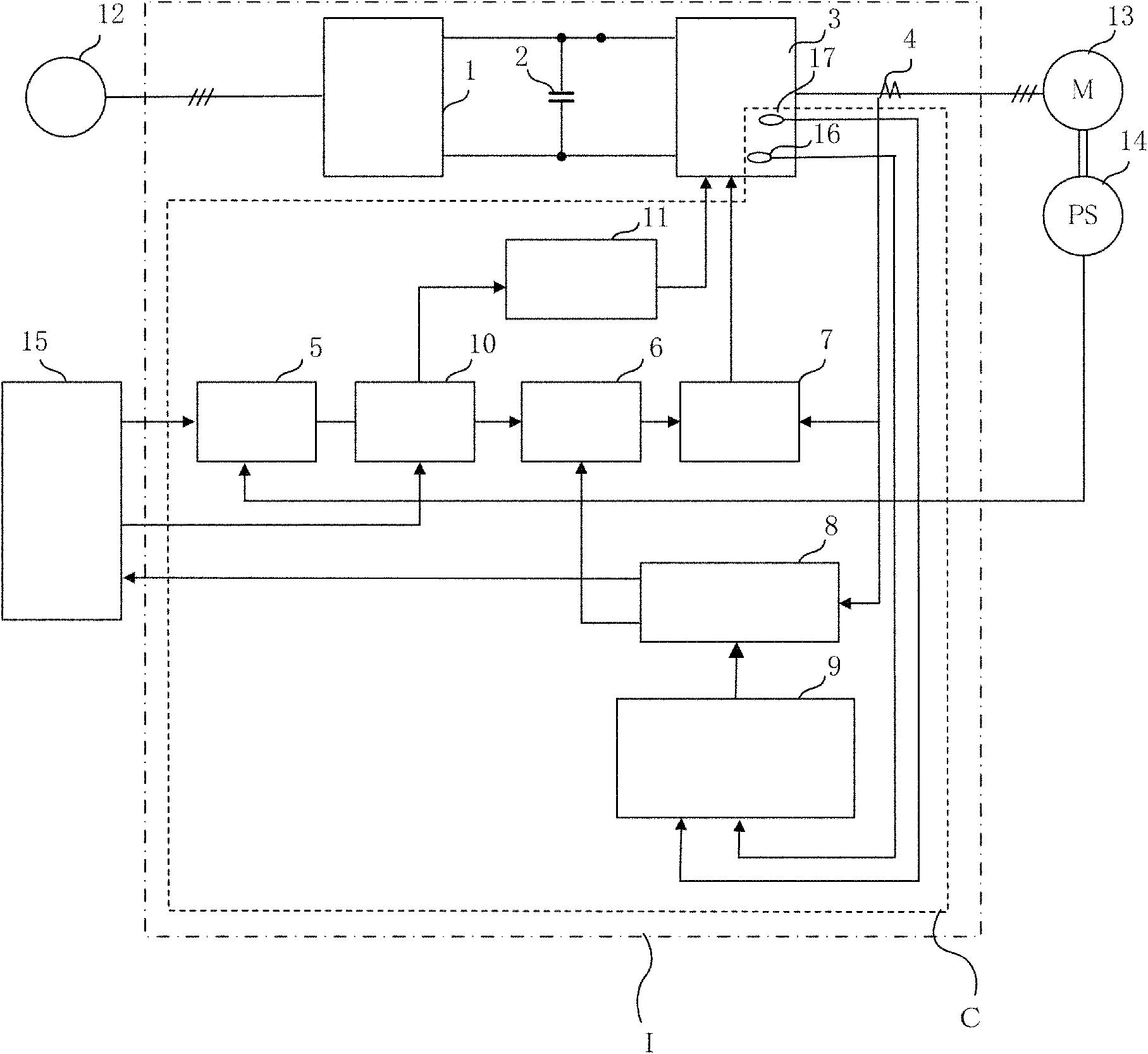
[0086] figure 1 The inverter device 1 of this embodiment is shown in . A power supply 12 for supplying electric power to the inverter device 1 is provided outside the inverter device 1 . A high-level controller 15 such as a CPU that controls the inverter device 1 is also provided outside the inverter device 1. The inverter device 1, the power supply 12, and the host controller 15 are collectively referred to as an inverter control system.

[0087] The motor 13 controlled by the inverter device 1 and the position detection unit 14 for detecting the position of the motor are provided outside the inverter device 1. The inverter device 1, the motor 13, and the position detection unit 14, or the structure in which the power supply 12 and the host controller 15 are added on this basis are collectively referred to as a motor control system.

[0088] The inverter device 1 of the present embodiment is composed of a control unit C, a converter unit 1, and an inverter unit 3. The co...


PUM


Abstract

Provided is an inverter apparatus that includes a power module mounted on an unknown heat sink and that realizes overload protection while maintaining a high performance of the apparatus. An inverter apparatus (I) includes a heat sink, an inverter (3) that includes a semiconductor device and that is attached to the heat sink, detectors (16, 17) that detect the temperature of the inverter (3), an estimator (9) that calculates estimated values of the thermal resistance and the thermal capacity of the heat sink on the basis of the temperature detected by the detectors (16, 17), and a controller C that controls driving of the inverter (3) on the basis of the estimated values.

Description

technical field [0001] The invention relates to an inverter device and a control method thereof, in particular to a protection function during overload. Background technique [0002] As a conventional structure, there exists, for example, the structure described in Unexamined-Japanese-Patent No. 2002-345147 (patent document 1). Patent Document 1 proposes a technology for maintaining the maximum output of the motor while maintaining the maximum output of the motor even when the operating conditions or ambient temperature change (hereinafter referred to as "overload protection"). The surface temperature and internal temperature of the motor are obtained from a thermal model that takes heat generation and ambient temperature as variables. [0003] Japanese Patent Application Laid-Open No. 10-164703 (Patent Document 2) proposes a technology that maintains the maximum output even when operating conditions such as a stopped state or an ultra-low-speed rotation state of the motor ...

Claims


Application Information

Patent Timeline
Patent Type & Authority Applications(China)
IPC IPC(8): H02M7/48H02M7/5387H05K7/20H02P29/00
CPCH02P8/12H02M7/53875H02P29/0088H05K7/20945H02M7/48H02P29/68
Inventor 佐佐木亮下池正一郎
Owner YASKAWA DENKI KK
Why Eureka
Try Eureka