Direct current rotary cultivator

A technology of rotary tiller and DC motor, applied in the field of rotary tiller, can solve the problems of loud noise, inconvenient use, difficult to pull, etc., and achieve the effects of noise reduction, convenient operation and light overall weight

Inactive Publication Date: 2011-08-17
CHANGZHOU SIMADE POWER EQUIP MFG
View PDF4 Cites 2 Cited by
  • Summary
  • Abstract
  • Description
  • Claims
  • Application Information

AI Technical Summary

Problems solved by technology

[0002] At present, the power devices of the rotary tillers on the market are mainly fuel engines and AC motors. The fuel engines are expensive to use, relatively loud, and the emissions are not environmentally friendly.

Method used


Image

  • Direct current rotary cultivator
  • Direct current rotary cultivator
  • Direct current rotary cultivator

Examples


Embodiment Construction

[0010] The present invention will be described in further detail below in conjunction with the accompanying drawings and embodiments.

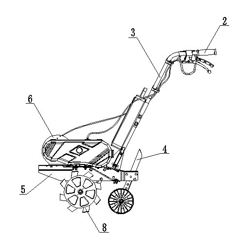
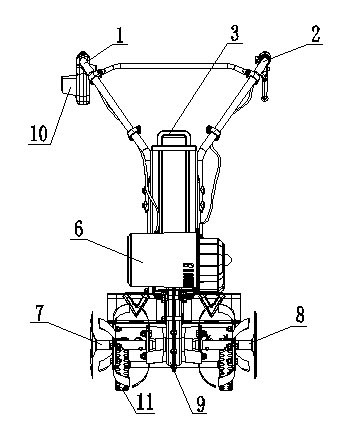
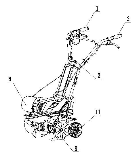
[0011] Such as Figure 1~3 As shown, a DC rotary tiller includes a body 5, a left armrest assembly 2, a right armrest assembly 1, a left knife rest assembly 8, a right knife rest assembly 7, a knife insertion assembly 4, a switch box assembly 10, and a walking wheel assembly 11 And the transmission box 9, the output end of the transmission box 9 is connected with the knife shaft of the left tool rest assembly 8 and the right tool rest assembly 7 respectively, the switch box assembly 10 is contained on the left armrest assembly 2 or the right armrest assembly 1, and also includes a DC power supply 3 and the DC motor 6 installed on the body 5, the switch box assembly 10 and the DC power supply 3 are all connected to the DC motor 6 through wires, the output shaft of the DC motor 6 is connected to the input end of the transmission box 9, and the D...


PUM


Abstract

The invention relates to a direct current rotary cultivator, which comprises a machine body (5), a left handrail component (2), a right handrail component (1), a left knife rest component (8), a right knife rest component (7), a slotting tool component (4), a switch box component (10), a walking wheel component (11) and a transmission box (9), wherein an output end of the transmission box (9) is respectively connected to the knife pivots of the left knife rest component (8) and the right knife rest component (7); the switch box component (10) is arranged on the left handrail component (2) or the right handrail component (1); the direct current rotary cultivator also comprises a direct current power supply (3) and a direct current motor (6) installed on the machine body (5); the switch box component (10) and the direct current power supply (3) are both connected to the direct current motor (6) through leads; and an output shaft of the direct current motor (6) is connected to an input end of the transmission box (9). The direct current motor is used as a driving device of the direct current rotary cultivator, no externally connected power line and no diesel oil or gasoline are required, and the direct current rotary cultivator has the advantages that the noise is low, the energy is saved, the environment is protected, and the operation is convenient.

Description

technical field [0001] The invention relates to the field of rotary tillers, in particular to a DC rotary tiller used for farming in gardens and agricultural areas. Background technique [0002] At present, the power devices of rotary tillers on the market are mainly fuel engines and AC motors. Fuel engines are expensive to use, relatively loud, and their emissions are not environmentally friendly. Moreover, fuel engines are heavy and difficult to pull. However, the AC motor needs to be connected to an external power supply through a power cord, which is inconvenient to use and has potential safety hazards. Contents of the invention [0003] The object of the present invention is to provide a DC rotary cultivator with convenient operation, energy saving and environmental protection. [0004] The technical solution for achieving the above purpose is: a DC rotary cultivator, including a body, a left handrail assembly, a right handrail assembly, a left knife rest assembly, a...

Claims


Application Information

Patent Timeline
IPC IPC(8): A01B33/08
Inventor 管政宪
Owner CHANGZHOU SIMADE POWER EQUIP MFG
Why Eureka
Try Eureka