Mold, device and method for punching chip component ceramic diaphragm

A technology of ceramic diaphragm and punching equipment, which is applied in the field of punching ceramic materials, can solve the problems of high cost, expensive punching equipment, and limited aperture size, and achieve low production cost, good consistency, and easy mass production Effect

Active Publication Date: 2013-12-25
SHENZHEN SUNLORD ELECTRONICS
View PDF15 Cites 0 Cited by
  • Summary
  • Abstract
  • Description
  • Claims
  • Application Information

AI Technical Summary

Problems solved by technology

[0003] The technical problem to be solved by the present invention is to provide a punching mold, punching equipment and a punching method for a ceramic diaphragm of a chip element to make up for the shortcomings of the limited aperture size, expensive punching equipment, and high cost in the prior art.

Method used


Image

  • Mold, device and method for punching chip component ceramic diaphragm
  • Mold, device and method for punching chip component ceramic diaphragm
  • Mold, device and method for punching chip component ceramic diaphragm

Examples


Embodiment Construction

[0036] The present invention will be described in detail below with reference to the accompanying drawings and in combination with preferred specific embodiments.

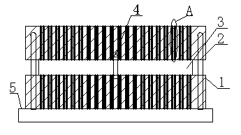
[0037] In one embodiment, the punching mold of the ceramic diaphragm of the chip element includes an upper mold, a lower mold and a fixed positioning device, and the upper mold and the lower mold are correspondingly provided with an upper mold hole and a lower mold hole. When in use, the The ceramic diaphragm is fixed and positioned between the upper mold and the lower mold by the fixing and positioning device.

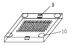
[0038] Such as Figure 1-5 As shown, specifically, preferably, the punching mold includes an upper mold 2, a lower mold 1, a fixed positioning device, an initial positioning hole 10 and a base 5, and the upper mold 2 and the lower mold 1 are correspondingly provided with an upper mold hole and a lower mold hole. The mold hole, the fixed positioning device includes a positioning hole 9 and a positioning pi...


PUM

PropertyMeasurementUnit
thicknessaaaaaaaaaa

Abstract

The invention discloses a mold, a device and a method for punching a chip component ceramic diaphragm. The punching mold comprises an upper mold, a lower mold and a fixing and positioning device, wherein an upper mold hole and a lower mold hole are correspondingly formed on the upper and lower molds. The punching device comprises a high-pressure water injector and the punching mold, wherein the high-pressure water injector is arranged directly opposite to the upper mold; and when the punching device is used, the ceramic diaphragm is fixed on the positioning device and positioned between the upper mold and the lower mold, and the water injected from the high-pressure water injector breaks through the ceramic diaphragm. The punching method comprises: 1) placing the ceramic diaphragm between the upper mold and the lower mold, 2) fixing and positioning the ceramic diaphragm between the aligned upper mold hole and lower mold hole by using the fixing and positioning device; and 3) allowing the high-pressure water injector to inject water to break through the ceramic diaphragm. The mold, the device and the method have the advantages that: the equipment investment is low; the maintenance cost is low; the device is simply operated; the production cost is low; and the mold, the device and the method can be widely applied to punching of electronic component ceramic materials.

Description

technical field [0001] The invention relates to the punching of ceramic materials, in particular to a punching mold, punching equipment and a punching method for ceramic diaphragms of chip components. Background technique [0002] At present, the equipment for drilling ceramic diaphragms on the market mainly includes mechanical drilling and laser drilling. Laser drilling is to generate non-divergent strong light-laser when excited by the same energy as the natural oscillation frequency of its molecules. It uses the characteristics of high energy and high focus of the laser to achieve drilling. Traditional mechanical drilling is hindered by the diameter of the drill. If it is too small, the size of the hole is limited, and these two punching devices are very expensive and the maintenance cost is quite high. Contents of the invention [0003] The technical problem to be solved by the present invention is to provide a punching die, punching equipment and a punching method fo...

Claims


Application Information

Patent Timeline
Patent Type & Authority Patents(China)
IPC IPC(8): B28D1/14
Inventor 祝小青黄德林曾艳军黄佑新雷奇邵庆云曾向东彭朝阳
Owner SHENZHEN SUNLORD ELECTRONICS
Why Eureka
Try Eureka