Power distribution control method and system for mobile operation machine

A technology for mobile operation and control methods, applied in the direction of control devices, transportation and packaging, vehicle components, etc., can solve problems such as hydraulic loss, disparity, etc.

Inactive Publication Date: 2011-08-17
JIANGSU LIUGONG MACHINERY +1
View PDF5 Cites 13 Cited by
  • Summary
  • Abstract
  • Description
  • Claims
  • Application Information

AI Technical Summary

Problems solved by technology

The traditional hydraulic system uses a quantitative pump to supply oil to each hydraulic component. For different working conditions, the required hydraulic oil flow rate is also different.

Method used


Image

  • Power distribution control method and system for mobile operation machine
  • Power distribution control method and system for mobile operation machine
  • Power distribution control method and system for mobile operation machine

Examples


Embodiment 1

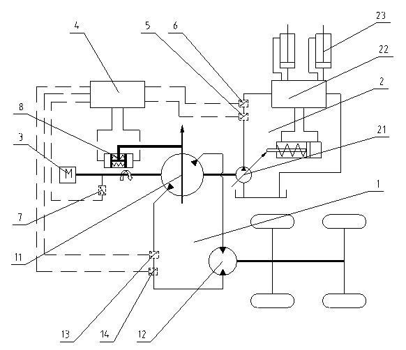
[0028] Embodiment 1: as figure 1 As shown, the power distribution control system of the mobile working machine includes a traveling hydraulic system 1, a working hydraulic system 2 and an engine system 3, the traveling hydraulic system 1 includes a traveling pump 11 and a traveling motor 12, and the working hydraulic system 2 includes a working pump 21 and a The element 23 , the walking pump 11 and the working pump 21 are connected with the engine system 3 , therefore, the walking pump 11 and the working pump 21 are linked with the engine system 3 . The power distribution control system also includes flow sensors 5 and 14 for measuring the flow of the working hydraulic system 2 and the traveling hydraulic system 1, pressure sensors 6 and 13 for measuring the pressure of the working hydraulic system 2 and the traveling hydraulic system 1, and a speed sensor for measuring the engine speed 7. The controller 4 that receives the signals of the flow sensors 5, 14, the pressure senso...

Embodiment 2

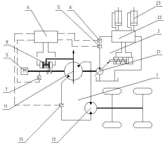
[0033] Embodiment 2: as figure 2As shown, the power distribution control system of the mobile working machine includes a traveling hydraulic system 1, a working hydraulic system 2 and an engine system 3, the traveling hydraulic system 1 includes a traveling pump 11 and a traveling motor 12, and the working hydraulic system 2 includes a working pump 21 and a The element 23 , the walking pump 11 and the working pump 21 are connected with the engine system 3 , therefore, the walking pump 11 and the working pump 21 are linked with the engine system 3 . The power distribution control system also includes a flow sensor 5 for measuring the flow of the working hydraulic system 2, pressure sensors 6 and 13 for measuring the pressure of the working hydraulic system 2 and the walking hydraulic system 1, and a speed sensor 7 for measuring the engine speed, receiving the flow sensor 5 and the controller 4 of the pressure sensor 6,13 and the speed sensor 7 signals and the displacement cont...


PUM


Abstract

The invention relates to a power distribution control method and a power distribution control system for a mobile operation machine. The power distribution control system comprises a traveling hydraulic system, a working hydraulic system, an engine system, a flow sensor, a pressure sensor, a rotating speed sensor, a controller and a discharge capacity controller, wherein the traveling hydraulic system and the working hydraulic system are driven by the engine system; the flow sensor is used for measuring the flow of the working hydraulic system; the pressure sensor is used for measuring pressure of the working hydraulic system and the traveling hydraulic system; the rotating speed sensor is used for measuring rotating speed of an engine; the controller is used for receiving signals of the sensors; and the discharge capacity controller is used for controlling the discharge capacity of a traveling pump. Power of the working hydraulic system and maximum theoretical output power of the engine at the current rotating speed are calculated by the controller. When the sum of the power of the working hydraulic system and the power of the traveling hydraulic system achieves the maximum theoretical output power of the engine, the power of the traveling hydraulic system is reduced by the controller. By the power distribution control system, not only can the working hydraulic system be ensured to obtain the maximum power, but also the engine is prevented from shutting down due to overload.

Description

technical field [0001] The invention relates to a mobile operating machine control method and system, in particular to a power distribution control method and system for a working hydraulic system and a traveling hydraulic system of a mobile operating machine. Background technique [0002] Traditional mobile working machinery includes two important systems, the working hydraulic system and the traveling hydraulic system, which are generally driven by engines. The power of the hydraulic system is equal to the product of the pressure of the system and the flow rate of the hydraulic oil in the system, while the pressure of the hydraulic system is determined by the load, and the flow rate of the hydraulic oil is equal to the product of the displacement and the rotational speed of the hydraulic pump, so the control hydraulic system mainly It is the control of the displacement and speed of the hydraulic pump. The output power of the engine is equal to the product of the rotationa...

Claims


Application Information

Patent Timeline
IPC IPC(8): B60W10/06B60W10/30B60W40/10B60K17/10
Inventor 罗石忠牛宏杰邵年陈晋市杜丹刘昕晖
Owner JIANGSU LIUGONG MACHINERY
Why Eureka
Try Eureka