Seaming method of underground diaphragm wall

An underground continuous wall and hinged pipe technology, applied in sheet pile wall, construction, infrastructure engineering, etc., can solve the problem of difficult cleaning of slag or local mud, uneven force on the cleaning surface, and bulky steel cages, etc. To solve the problem of cleaning and brushing, ensure the effect of brushing mud, and achieve the effect of simple construction method

Active Publication Date: 2011-08-17
SHANGHAI YUANFANG GROUNDWORK ENG
View PDF4 Cites 9 Cited by
  • Summary
  • Abstract
  • Description
  • Claims
  • Application Information

AI Technical Summary

Problems solved by technology

At present, most of the seams in China use lock pipe joints and I-shaped prefabricated joints. During construction, when the unit groove section is placed during the excavation process of the groove forming machine, it is necessary to use a wall brush to clean the contact surface of the first poured groove section. Scrubbing, because the surface of the contact surface is the side of the steel cage, not the overall smooth surface, and because the steel cage is bulky and deep, it is difficult for the wall brusher to keep fixed with the cleaning surface when cleaning up and down. Due to the above-mentioned problems in the cleaning work, it is difficult to clean the sediment or local mud at the joints of the groove section, which will easily lead to seepage in the later stage. water leakage

Method used


Image

  • Seaming method of underground diaphragm wall
  • Seaming method of underground diaphragm wall
  • Seaming method of underground diaphragm wall

Examples


Embodiment Construction

[0018] The features of the present invention and other related features will be further described in detail below in conjunction with the accompanying drawings through embodiments, so as to facilitate the understanding of those skilled in the art:

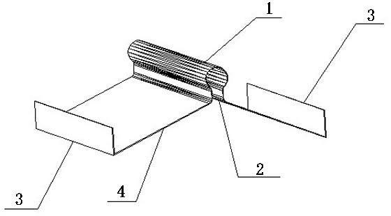
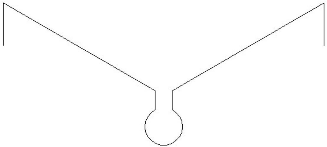
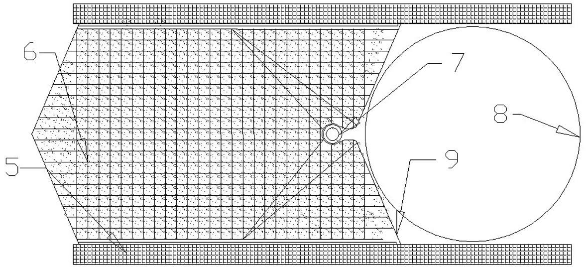
[0019] like Figure 1-5 As shown, the total reference numerals 1-15 represent respectively: hinged pipe 1, hinged pipe opening 2, hemming part 3, wing plate 4, guide wall 5, reinforced cage for pouring concrete 6, drawing rubber 7, lock pipe 8. Articulated joint 9, water stop plate 10, guide roller 11, V-shaped wall brush 12, wire brush 13, rectangular box 14, V-shaped frame 15.

[0020] like Figure 1-2 As shown, the hinged joint 9 of the underground diaphragm wall involved in this embodiment is composed of a hinged tube 1, a hemming part 3, and a wing plate 4. The end face of the hinged tube 1 is approximately Ω-shaped, with a partial opening. The two ends of each are respectively connected to the wing plate 4, and the outer ed...


PUM


Abstract

The invention relates to underground buildings, in particular relates to a seaming method of an underground diaphragm wall. The method comprises the following steps that: an approximately V-shaped platy structure is mounted at the seam crossing of unit walls; hinge pipes are arranged at the top end of the V-shaped platy structure so as to realize a guide function; corresponding guide rollers are matched for guiding when a wall brushing device is used for cleaning, and enabling the wall brushing device to vertically brush the wall along a guide device formed by the hinge pipes, thereby ensuring mud brushing effect and greatly reducing the working load of leak prevention; or the corresponding guide rollers are also can be used for the guide device when locking notch tubes are submerged so as to ensure the accurate submergence position of the locking notch tubes and improve the working efficiency and the project quality; simultaneously, due to the presence of wing plates and flanged parts, the contact surface of the firstly-cast groove section has continuous and smooth planes except the local openings of the hinge pipes; therefore, the surface of the firstly-cast groove section is conveniently cleaned and brushed; and the locking notch tubes are conveniently pulled. According to the method of the invention, the problems of retention of the contact surface of the firstly-cast groove section or difficult clamped mud cleaning and brushing are excellently solved so that the seam crossing is closer; and the leakage in the seam is prevented.

Description

technical field [0001] The invention relates to underground buildings, in particular to an underground continuous wall joint method. Background technique [0002] The compactness of the joints of the underground diaphragm wall groove section is very important. If there is a problem with the construction quality of the joints, it will lead to leakage of the underground structure of the project, which will directly affect the use of the underground structure of the project. Leakage will not only affect the use function of the building , and it is very difficult to deal with, so effective measures must be taken during the construction of unit wall joints to solve the hidden problems in advance, so as to avoid future troubles. As an integral part of the underground main structure, the underground diaphragm wall must be permanent and durable, with no seepage, no leakage, and balanced stress in the whole structure. The walls of each unit groove section of the underground diaphrag...

Claims


Application Information

Patent Timeline
Patent Type & Authority Applications(China)
IPC IPC(8): E02D5/20
Inventor 刘忠池姚海明李睿张中亮
Owner SHANGHAI YUANFANG GROUNDWORK ENG
Why Eureka
Try Eureka