
Method and device for lapping section steel reinforced concrete beam with section steel columns

A technology of concrete beams and lap joints, which is applied in the processing of building materials, construction, building construction, etc., can solve the problems of steel column strength damage and affect the quality of construction, so as to achieve complete grouting, avoid blocking, and ensure construction quality Effect

Inactive Publication Date: 2011-08-17
广州市建筑集团有限公司 +1
View PDF4 Cites 5 Cited by
  • Summary
  • Abstract
  • Description
  • Claims
  • Application Information

AI Technical Summary

Problems solved by technology

The method adopted in the prior art is to open holes in the shaped steel columns, specifically: each longitudinal steel bar of the steel concrete beam corresponds to opening a hole in the shaped steel columns, so that the longitudinal steel bars pass through the holes and are anchored in the shaped steel columns. Due to the large number and dense distribution of longitudinal steel bars, it is bound to make dense holes in the steel column, which will greatly damage the strength of the steel column and seriously affect the quality of construction.

Method used


Image

  • Method and device for lapping section steel reinforced concrete beam with section steel columns
  • Method and device for lapping section steel reinforced concrete beam with section steel columns
  • Method and device for lapping section steel reinforced concrete beam with section steel columns

Examples


Embodiment Construction

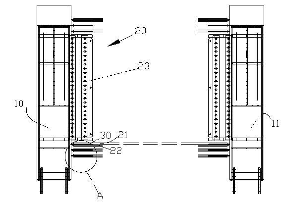
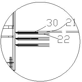
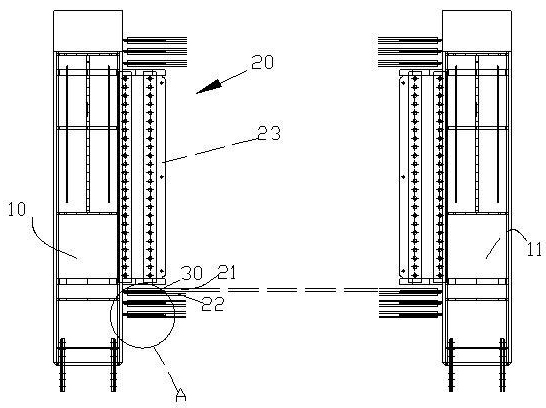
[0017] figure 1 Shown is a schematic diagram of the overlapping installation of a steel concrete beam and a steel column; wherein the steel concrete beam 20 is installed between the steel columns 10 on both sides, and the steel concrete beam 20 includes an internal steel 23 and longitudinal steel bars arranged around the internal steel 23 ( because figure 1 It is a schematic cross-sectional view, so only the reinforcing bars on the upper and lower sides of the internal shaped steel 23 can be seen). During construction, firstly connect sections of longitudinal steel bars correspondingly to the shaped steel columns; then measure the port straight thread spacing of the longitudinal steel bars correspondingly fixed on both sides of the shaped steel columns, and then cut the longitudinal steel bars; finally carry out Concrete cast steel concrete columns. Wherein, any appropriate method in the prior art may be used for cutting steel bars, which will not be repeated here.

[0018]...


PUM


Abstract

The invention relates to a method for lapping a section steel reinforced concrete beam with section steel columns. The section steel reinforced concrete beam is provided with a plurality of longitudinal steel bars arranged along the longitudinal direction of the section steel reinforced concrete beam. The method comprises the following steps of: (1) fixing the longitudinal steel bars in parallel on steel bar supporting plates one section after another and fixing a layer of longitudinal steel bars on the two faces of each steel bar supporting plate respectively, wherein the longitudinal steel bars on each steel bar supporting plate correspond one by one; and (2) fixing the steel bar supporting plates on which the longitudinal steel bars are fixed on the section steel columns, wherein the plurality of steel bar supporting plates are vertical to the axes of the section steel columns, the steel bar supporting plates fixed on different section steel columns correspond one by one, and the longitudinal steel bars on corresponding steel bar supporting plates fixed on different section steel columns are opposite one by one. By adopting the lapping method, stable lapping can be realized, the section steel columns are prevented from being damaged, and the construction quality is ensured. Moreover, the invention also provides a device for lapping the section steel reinforced concrete beam with the section steel columns.

Description

technical field [0001] The invention belongs to the field of civil engineering, and relates to a method for lapping longitudinal reinforcement and a steel column of a steel concrete beam in a steel concrete structure and a device used therefor. Background technique [0002] During construction, it is necessary to overlap the shaped steel column and the shaped steel concrete beam; and to overlap the two is to solve the problem of how to overlap the longitudinal reinforcement of the shaped steel concrete beam on the shaped steel column. The method adopted in the prior art is to open holes in the shaped steel columns, specifically: each longitudinal steel bar of the steel concrete beam corresponds to opening a hole in the shaped steel columns, so that the longitudinal steel bars pass through the holes and are anchored in the shaped steel columns. Due to the large number and dense distribution of longitudinal steel bars, it is bound to make a plurality of dense holes in the stee...

Claims


Application Information

Patent Timeline
IPC IPC(8): E04G21/00E04B1/41E04B1/58E04B1/38
Inventor 苏建华胡志桥高俊岳吴瑞卿梁艺铭许建锋梁荣湛符志文江德机黄日龙邓志翔黄立新袁爱珍冯伟
Owner 广州市建筑集团有限公司
Learn More