Lever system for pumping unit

A technology of pumping units and levers, which is applied in mechanical equipment, machines/engines, liquid variable capacity machinery, etc. It can solve the problems of small output power of power output components, relatively high power output requirements, and large energy consumption of pumping units. , to achieve the effect of reducing power output requirements, reducing energy consumption, and reducing driving torque

Inactive Publication Date: 2011-08-17
吕传庆
View PDF8 Cites 8 Cited by
  • Summary
  • Abstract
  • Description
  • Claims
  • Application Information

AI Technical Summary

Problems solved by technology

[0005] In view of this, the present invention provides a pumping unit that not only consumes less energy, but also has a relatively small output power of the power output components in order to overcome the defects of high energy consumption and relatively high power output requirements of current pumping units. machine lever system

Method used


Image

  • Lever system for pumping unit
  • Lever system for pumping unit
  • Lever system for pumping unit

Examples


Embodiment Construction

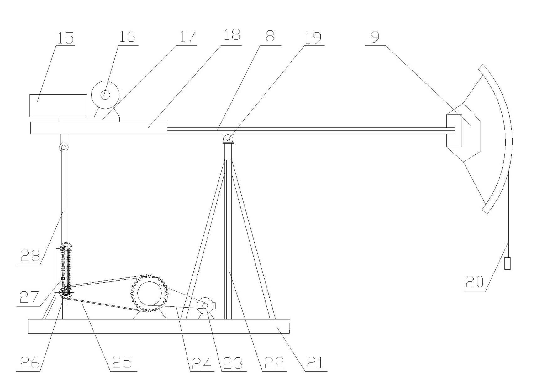
[0035] According to the present invention, with reference to the attached image 3 , which shows a pumping unit lever system comprising:

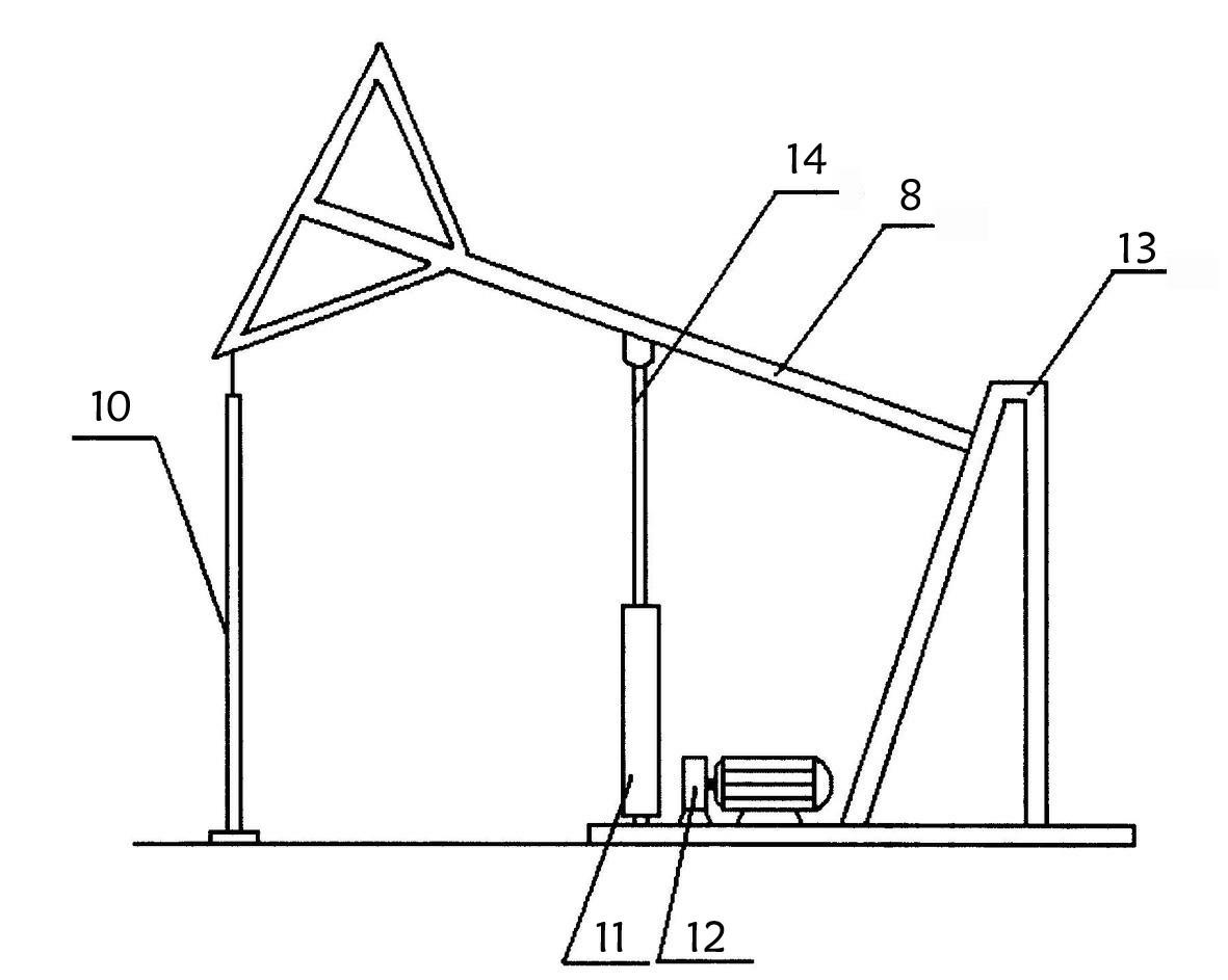
[0036] The main support 22 can be equivalent to the attached figure 2 The bracket shown in is mainly used as a fixed hinge support, that is, a mounting bracket for the hinge support;

[0037] The traveling beam 8, the middle part is installed on the top of the main bracket 22 through a hinge, forming a basic lever mechanism;

[0038] The donkey head 9 is arranged at one end of the beam, which is on the side of the sucker rod, connected to the sucker rod through the rope hanger 20, and the sucker rod is installed on the oil outlet tee at the wellhead through the wellhead packing seat;

[0039] It also includes:

[0040] Pull rod 28, the upper end of the pull rod is hinged to the other end of the beam. Of course, the pull rod also has the function of pushing. When the head of the donkey goes down, it needs to be driven by the pull rod. At...


PUM


Abstract

The invention discloses a lever system for a pumping unit. The lever system comprises a main support, a walking beam, a horse head, a pull rod hinged at the other end of the walking beam, a first drive device, a detecting device which is arranged on a stand for detecting upward or downward state of the pull rod, a rail formed at the pull rod side of the walking beam, a sliding seat matched with the rail to form a rail pair, a counter weight arranged on the sliding seat, and a second drive device for driving the sliding seat to run according to the pull rod state detected by the detecting device to ensure that the sliding seat is close to a constraint hinge when the pull rod moves upward and the sliding seat is far from the sliding seat when the pull rod moves downward, therefore, the lever system has small energy consumption and smaller output power of a power output part.

Description

technical field [0001] The invention relates to a lever system of an oil pumping unit. Background technique [0002] The widely used pumping unit at present is the beam pumping unit. Its main structure is a lever mechanism, which is called beam system in the industry. One end of the lever is the donkey head connected with the sucker rod, and the other end is the driving end. The pull rod is connected with a crank, and the end of the crank is provided with a relatively heavy counterweight, and the driving force of the lever is realized by using the different characteristics of the direction and magnitude of the force within the range of 360 degrees of the crank. For the pumping unit with this structure, the output power of each cycle of the crank rotation is basically unchanged, and it is always in a state of high power output, or in a state of high energy consumption. High energy consumption is also difficult to solve for this type of pumping unit. question. [0003] For t...

Claims


Application Information

Patent Timeline
Patent Type & Authority Applications(China)
IPC IPC(8): E21B43/00F04B47/02F04B47/14
Inventor 吕传庆
Owner 吕传庆
Why Eureka
Try Eureka