
System calibration method of tire balancing machine

A tire balancing and system calibration technology, applied in static/dynamic balance testing, machine/structural component testing, and measuring devices, etc., can solve problems such as affecting measurement results, system calibration errors, and inability to guarantee absolute phase of measured rotational speed.

Active Publication Date: 2011-08-17
LAUNCH SOFTWARE DEV
View PDF4 Cites 6 Cited by
  • Summary
  • Abstract
  • Description
  • Claims
  • Application Information

AI Technical Summary

Problems solved by technology

However, in the implementation of the system calibration method of the tire balancer in the prior art, it does not take into account that there is an unbalance in the tire and the main shaft used for calibration, and that the rotation speed of each measurement during the measurement process cannot be guaranteed to be absolutely equal. This will bring errors to the system calibration and affect the measurement results.

Method used


Image

  • System calibration method of tire balancing machine
  • System calibration method of tire balancing machine
  • System calibration method of tire balancing machine

Examples


Embodiment Construction

[0043] In order to further illustrate the technical means adopted by the present invention and its effects, the following describes in detail in conjunction with preferred embodiments of the present invention and accompanying drawings.

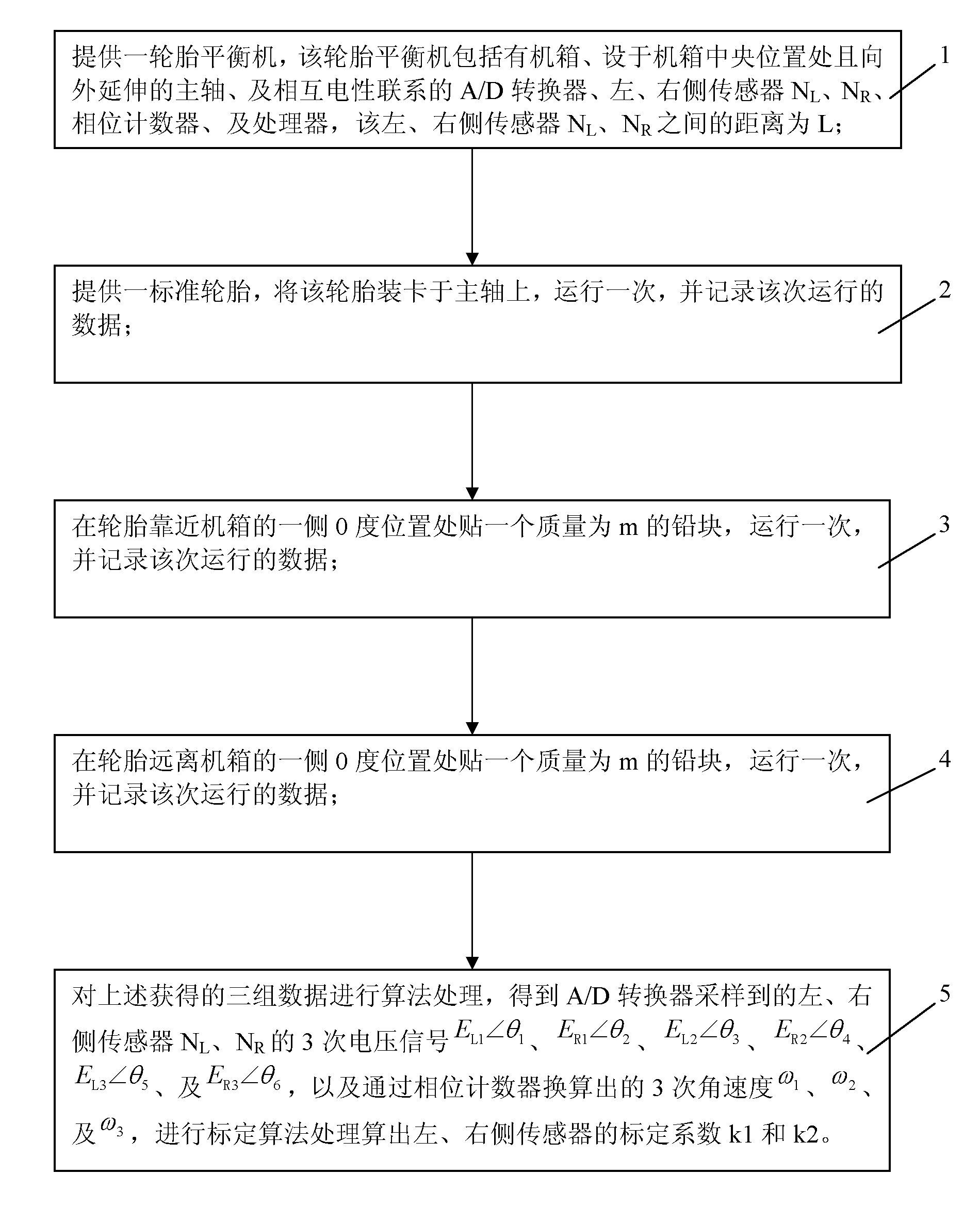
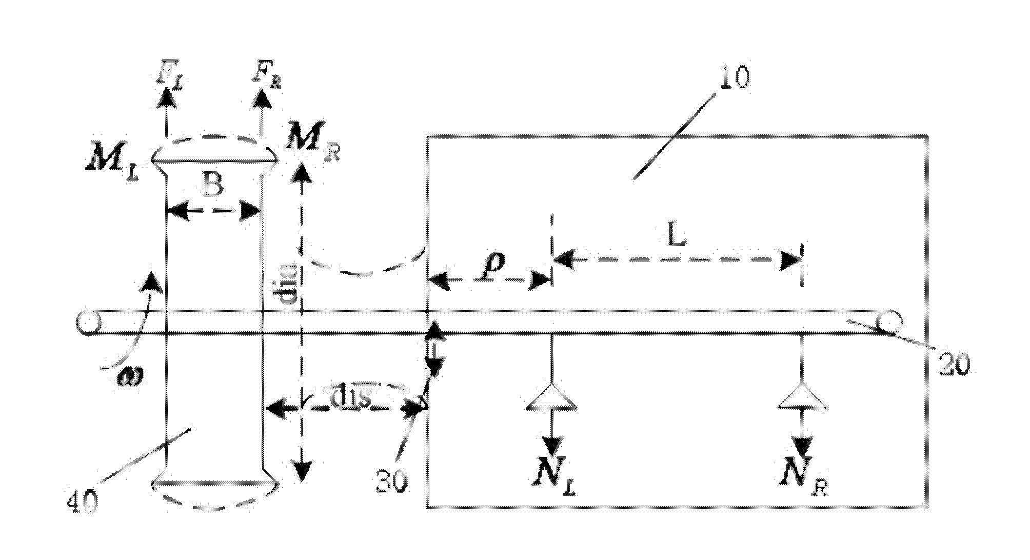
[0044] like figure 1 , 2 As shown, the present invention provides a system calibration method for a tire balancing machine, which includes:

[0045] Step 1, providing a tire balancing machine, which includes a chassis 10, a main shaft 20 located at the center of the chassis 10 and extending outwards, an A / D converter electrically connected to each other, left and right sensors N L , N R , phase counter 30, and processor (not shown), the left and right side sensors N L , N R The distance between them is L.

[0046] Step 2, provide a standard tire 40, clamp the tire 40 on the main shaft 20, run once, and record the data of this run. The tire 40 is mounted on the main shaft 20 and rotates, generating an induction force at the position of t...


PUM


Abstract

The invention provides a system calibration method of a tire balancing machine, comprising: step I, supplying a tire balancing machine; step II, supplying a standard tire, clamping the tire on a main shaft, running the tire once, and recording the running data; step III, pasting a lead m in weight at a 0-degree position at one side of the tire close to a case, running the lead once and recording the running data; step IV, pasting a lead m in weight at a 0-degree position at one side of the tire far away the case, running the lead once and recording the running data; step V, performing algorithm processes for the obtained three datum, and performing a calibration algorithm process to calculate the calibration coefficients k1 and k2 of left and right sensors. In the invention, before the tire balancing machine is used for measuring, the linear relation between an inductor force and an induction voltage signal of the sensor is calibrated, the calibration coefficients k1 and k2 of left and right sensors are determined, and the size and position of dynamic and static unbalance amount of the tire can be measured accurately, so that the error of the system calibration is reduced to the minimum value.

Description

technical field [0001] The invention relates to the technical field of tire testing, in particular to a system calibration method for tire dynamic balancing machine measurement. Background technique [0002] With the development of the automobile industry and the continuous growth of my country's automobile market, the demand for tire balancers is also increasing. However, the research and development and production of tire balancers in China are relatively backward. [0003] The unbalance of automobile tires is caused by the failure to eliminate the inertial force or centrifugal inertial force, and the unbalanced amount is a vector. During the tire manufacturing process, the center of gravity of the tire does not coincide with the center of the rotation axis, and when it rotates around the axle, it generates inertial forces of different sizes in various directions. Tire imbalance is divided into two types: static imbalance and dynamic imbalance. Tires with static imbalanc...

Claims


Application Information

Patent Timeline
Patent Type & Authority Applications(China)
IPC IPC(8): G01M1/28
Inventor 刘均林钢
Owner LAUNCH SOFTWARE DEV
Learn More