Electronic piano sound box device

A technology for electronic pianos and speakers, applied in the field of musical instruments, can solve problems such as poor acoustic effects, affecting visual effects, and unsatisfactory sound effects, and achieve sound radiation in a reasonable direction, expand low-frequency characteristics, and improve sound effects

Inactive Publication Date: 2011-08-17
马季平
View PDF7 Cites 2 Cited by
  • Summary
  • Abstract
  • Description
  • Claims
  • Application Information

AI Technical Summary

Problems solved by technology

The non-speaker structure means that the speakers are directly installed in the same piano box where the keyboard is installed, that is, the left and right channel speakers are installed in the same larger, non-airtight resonance box, which cannot fully express the sound field width and sound effect of the left and right channels. ;Most electronic pianos install the left and right channel speakers directly on the bottom plate of the open piano box for the convenience of installation and visual appearance, so that the radiation direction of the speakers is downward, and the sound is reflected by the ground and transmitted to the human ear. , the sound wave is attenuated, and the acoustic effect is very poor; in order to improve the sound quality, some manufacturers install the smaller tweeter on the panel facing the performer, while the slightly larger woofer is still installed on the bottom plate of the piano box with holes due to volume limitations. The low frequency is not improved, and the acoustic effect is not satisfactory
The sound box structure refers to adding an independen

Method used


Image

  • Electronic piano sound box device
  • Electronic piano sound box device
  • Electronic piano sound box device

Examples


Embodiment Construction

[0025] The present invention is described further in conjunction with accompanying drawing, and the manufacturing technology of this device is very clear to those skilled in the art.

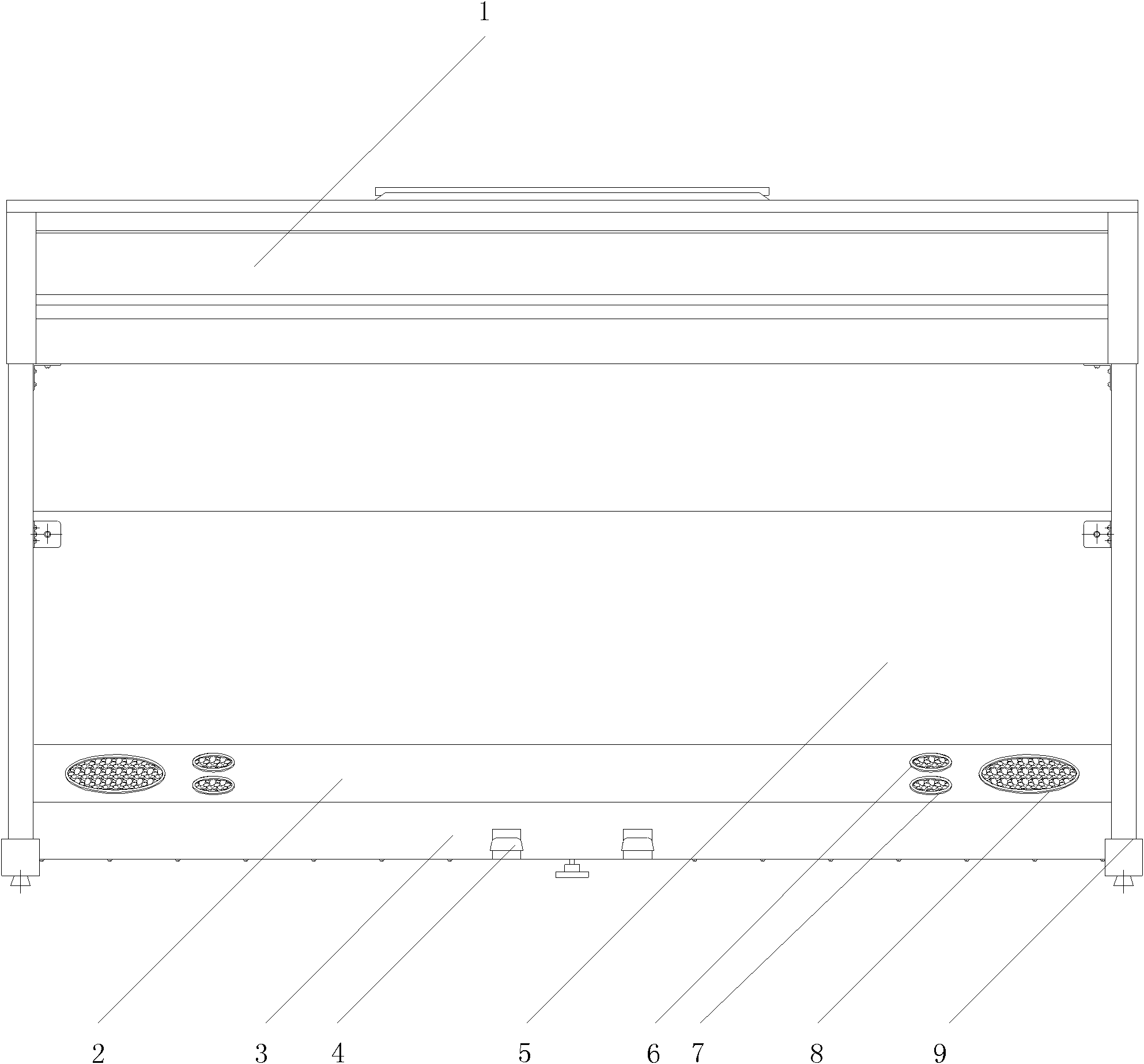
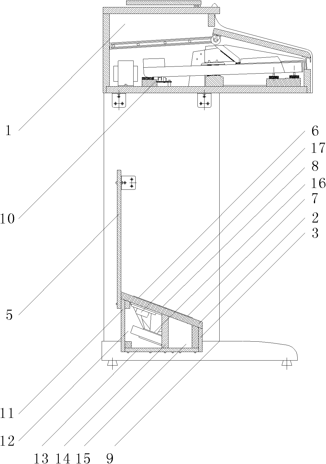
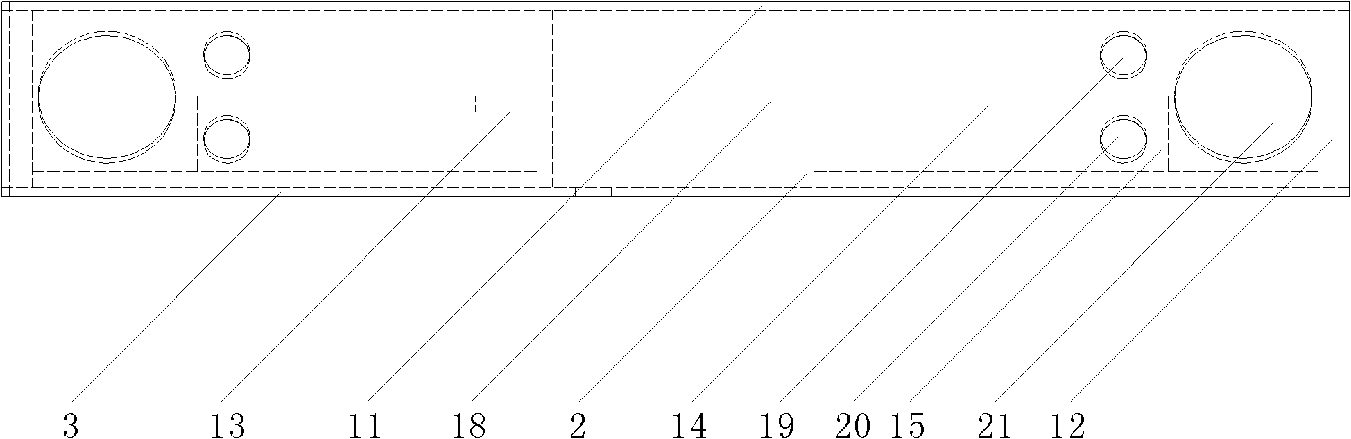
[0026] exist figure 1 Among them, the keyboard box (1) is the upper half of the electronic piano, and the structure below it is the lower half of the electronic piano. The left and right sides of the bottom surface of the piano keyboard box (1) are respectively connected with the left and right two groups of piano feet (9), and the left and right groups of piano feet (9) are respectively connected with the two sides of the lower cross plate (5), and are connected by the lower shelf panel (2) It is connected with the two ends of the lower gear formed by the lower gear front plate (3), the middle part of the lower gear is provided with a pedal group (4), and the left and right sides of the lower gear panel (2) surface are symmetrically provided with a subwoofer grille ( 8).

[0027] In the embod...


PUM


Abstract

The invention relates to an electronic piano sound box device, which is characterized by comprising a long groove body formed by splicing three long plates which are a lower crosspiece front plate, a lower crosspiece panel and a lower crosspiece rear plate; wherein two ends of the groove body are provided with edge supporting plates; the middle part of the groove body is provided with two middle supporting plates; a pedal set is connected between the two middle supporting plates; and two cover plates are arranged to respectively close a space formed by the edge supporting plates at the left and the right sides of the groove body, the middle supporting plates and the groove body so as to form two symmetrical sound box cavities which take the pedal set as the center. A certain inclined angle is formed between the lower crosspiece panel and the horizontal plane; the two ends of the lower crosspiece panel are symmetrically provided with loudspeaker holes and phase reversing holes; loudspeakers are respectively arranged on the loudspeaker holes on the lower crosspiece panel corresponding to the two sound box cavities; a short partition and a long partition are arranged to divide a phase reversing pipe in each loudspeaker cavity; and the phase reversing holes are communicated with the sound box cavities through the phase reversing pipe. Compared with the prior art, the electronic piano sound box device is novel and practical, and is capable of improving the loudspeaker effect and extending the function of the electronic piano as the active sound box.

Description

technical field [0001] The invention relates to the technical field of musical instruments, in particular to an electronic piano sound box device, in particular to the speaker sound box devices arranged on the left and right sides of the pedal structure at the lower end of the electronic piano. Background technique [0002] Electronic organ and electronic piano are electronic musical instruments that are produced by an electronic sound source, amplified by a circuit, and then output to a speaker for playback. The setting of the speaker and its installation structure directly affect the sound quality and sound effect of the electronic musical instrument. [0003] At present, the installation structures of speakers in electronic pianos and electronic pianos can be classified into two types: most of them are non-speaker structures, and a small part are speaker structures. The non-speaker structure means that the speakers are directly installed in the same piano box where the ke...

Claims


Application Information

Patent Timeline
IPC IPC(8): G10H1/32
Inventor 马季平
Owner 马季平
Why Eureka
Try Eureka