Inverse system-based active and reactive power independent control method for microgrid

A technology of active power and independent control, applied in the field of microgrid, can solve the problems of difficulty in independent adjustment of active and reactive power, unfavorable microgrid power flow regulation, etc.

Active Publication Date: 2013-04-17
NORTH CHINA ELECTRIC POWER UNIV (BAODING)
View PDF4 Cites 0 Cited by
  • Summary
  • Abstract
  • Description
  • Claims
  • Application Information

AI Technical Summary

Problems solved by technology

[0006] In view of the above-mentioned background technology, the mutual coupling of active power and reactive power in the existing micro-grid transmission line power makes it difficult to independently adjust active and reactive power, and is not conducive to the regulation of power flow in the micro-grid. The present invention proposes a Independent Control Method of Active and Reactive Power in Microgrid Based on Inverse System

Method used


Image

  • Inverse system-based active and reactive power independent control method for microgrid
  • Inverse system-based active and reactive power independent control method for microgrid
  • Inverse system-based active and reactive power independent control method for microgrid

Examples


specific Embodiment approach

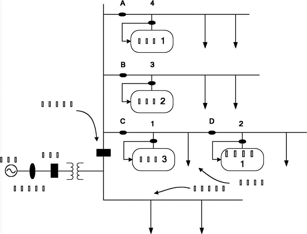
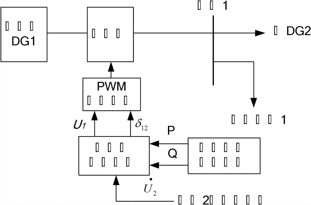
[0048] (1) The power transmission decision-making unit calculates the active power and reactive power that should be transmitted on the microgrid transmission line according to the output power and load of the micropower supply. Here, taking the control of micropower supply 1 as an example, it can be calculated by the following formula:

[0049] P = P DG 1 - P Load 1 Q = Q DG 1 - Q Load ...


PUM


Abstract

The invention discloses an inverse system-based active and reactive power independent control method for a microgrid in the technical field of the microgrid in a power system. The method comprises the following steps: firstly calculating active power and reactive power which need to be transmitted on a circuit connected with a controlled micro-power supply; further using a control unit of an inverse system to calculate effective value and phase of voltage outputted by the controlled micro-power supply according to the inputted active power and the reactive power; and finally using a pulse width modulation (PWM) control unit to calculate and emit a pulse signal according to the effective value and the phase of the voltage, controlling an inverter of the controlled micro-power supply, and realizing the control of transmission of the active power and the reactive power on the circuit. By adopting the method, the mutual coupling problem of the active power and the reactive power in power transmission through a transmission line in the microgrid is solved, and the control method is applicable to characteristics of parameters of the circuit in the microgrid and can precisely control thepower transmission and realize independent regulation of the active power and the reactive power.

Description

technical field [0001] The invention belongs to the technical field of micro-grids in power systems, and in particular relates to an independent control method for active and reactive power of micro-grids based on an inverse system. Background technique [0002] Microgrid is usually defined as a system composed of micropower sources (ie: Distributed Generation, DG in microgrids), energy storage devices and loads, such as figure 1 shown. In the figure, the micro-grid is composed of a group of radial feeders, which are connected to the large power grid through a common connection point. There are sensitive loads on the three feeders A, B, and C, and micro-power sources are needed to improve the reliability of power supply. There is no need for a micro power supply on the feeder. There are four micro-power sources at nodes 1, 2, 3, and 4. When the micro-grid operates independently, the sensitive load is disconnected from the distribution network, and the micro-power source pr...

Claims


Application Information

Patent Timeline
Patent Type & Authority Patents(China)
IPC IPC(8): H02J3/00H02J3/18
CPCY02E40/30
Inventor 李鹏马梦朝李雨薇魏喆刘承佳王阳
Owner NORTH CHINA ELECTRIC POWER UNIV (BAODING)
Why Eureka
Try Eureka